Program-controlled backlight of the Witcher figure series
The project of program-controlled backlighting of collector’s figurines combines the practical use of arduino IOT modules to provide program-controlled lighting effects as well as the application of LED lighting.
Requirements for the final proposal:
- the ability to independently control the light intensity and color tone of the light in a group of 6 collector’s figures,
- the selection of the backlight program mode must be possible by means of the IR remote control,
- the control module must be compactly integrated in the protective cover,
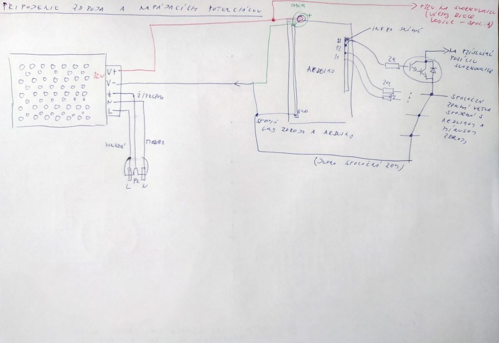
- the power supply is solved by means of a small pulse source,
- the output power must be sufficient for backlighting consisting of 2 * 3 RGB leds with a consumption of about 10mA per segment (expandable to 9 or 12 collector figures.
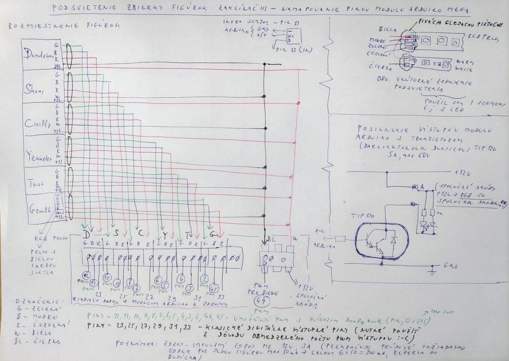
The control electronics module consists of a pulse power supply with an output of approximately 30VA. The Arduino Mega module was used as a control module due to the sufficient number of programmable PWM outputs. The PWM output makes it possible to ensure the gradual switching on and off of the individual light strips placed in the packaging of the collector’s figures.
Problems in the implementation phase and their solutions
In the conceptual design phase, despite the selected module, I encountered the problem of insufficient number of PWM outputs, which I solved by introducing a two-state control for the red backlight component (this is a compromise solution).
Power amplification of the outputs is achieved by using Darlington transistors TIP120 purchased from e-bay.
Description of the technical solution of the backlight
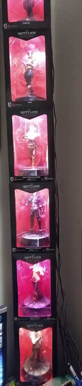
The backlight of each figure consists of a pair of LED strips, a part with warm white and an RGB strip. The pictures in the photo gallery show a more detailed link.
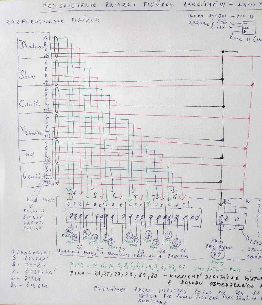
Block diagrams of electronics modules
The connection of the control module with the block of Darlington transistors is shown in the following figures (block interconnection diagrams).
The procedure for 3D printing of the protective cover is shown in the following photo gallery.
Demonstration of the control program
You can download one of the driver versions as an arduino sketch.
I firmly believe that this text will serve as inspiration for the backlighting of other collector’s collections.