1. Basic VoIP lab with two ephone for upcoming experiments
At first we must add second ephone (cheaper training solution is second cisco IP communicator) on VMware hosted client. As obvious install os on virtual PC. Next you need to configure network bridging with hosting pc. In our scenario hosting (physical PC) belong to network 172.16.0.0/24 with default gateway 172.16.0.1/24 and CME gateway was configured with 172.16.0.20/24, first ephone is on hosting pc with IP 172.16.0.10/24.
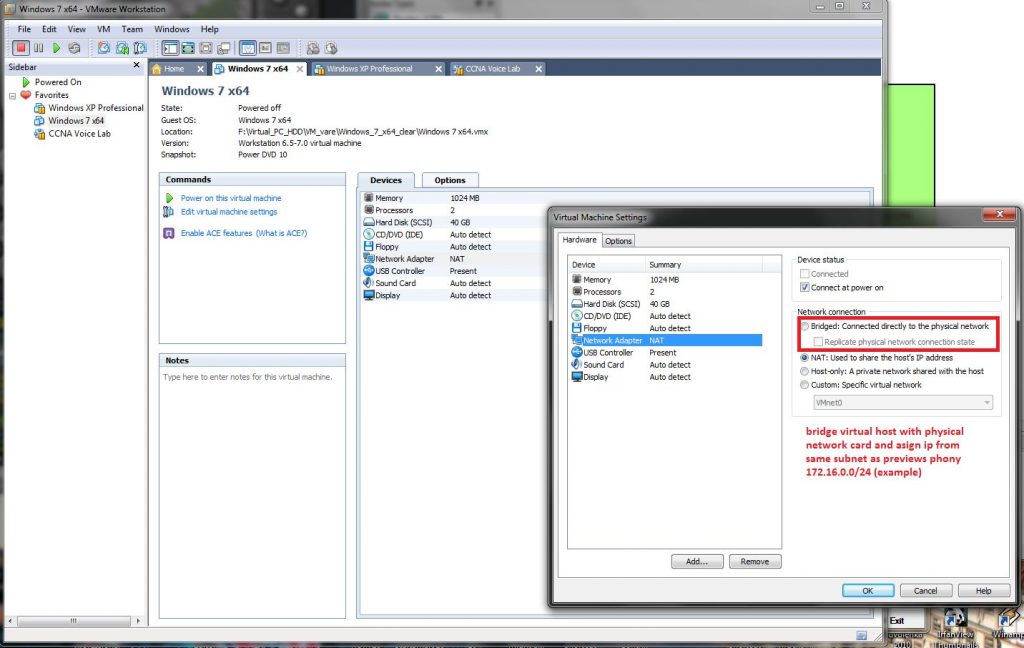
Setup process for bridging hosted pc to hosting network adapter is described in next pictures:
1) Open Virtual Network settings dialog and set bridged (not NAT)
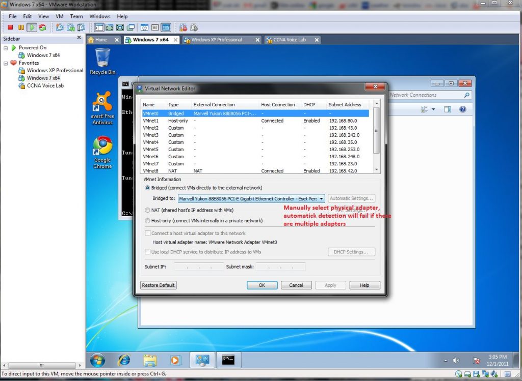
2) If you have more than one installed network adapter (WiFi, second network card, or virtual card of VMware) you must manually select appropriate bridging adapter as hosting client physical adapter (better is if you check it)
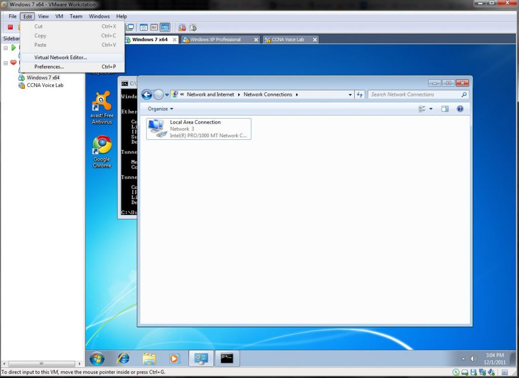
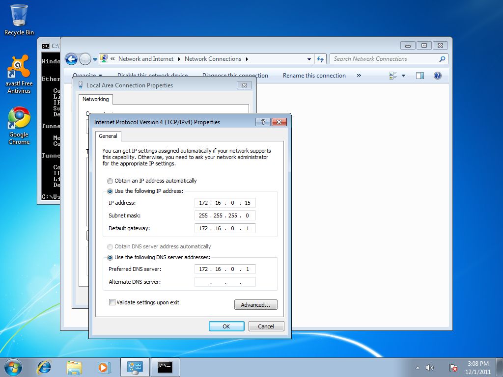
3) Configure IP address in hosted PC (in our scenario we used 172.16.0.15/24 and 172.16.0.1 as default gateway) -address assignment must be derived from your home network config – CME router and ephones are in this simple scenario in same subnet.
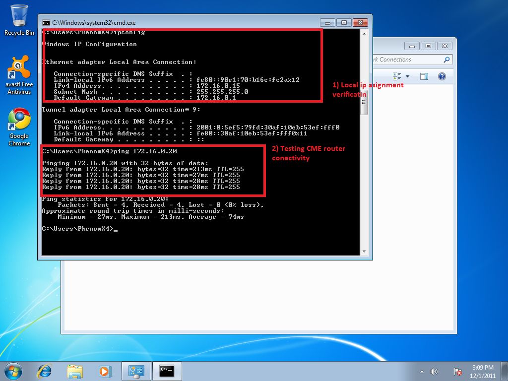
4) Verification of local stack and connectivity with CME router 172.16.0.20/24 from hosted PC (installed in VMware)
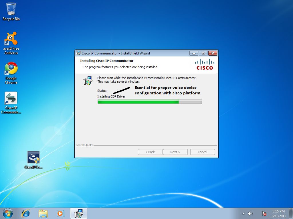
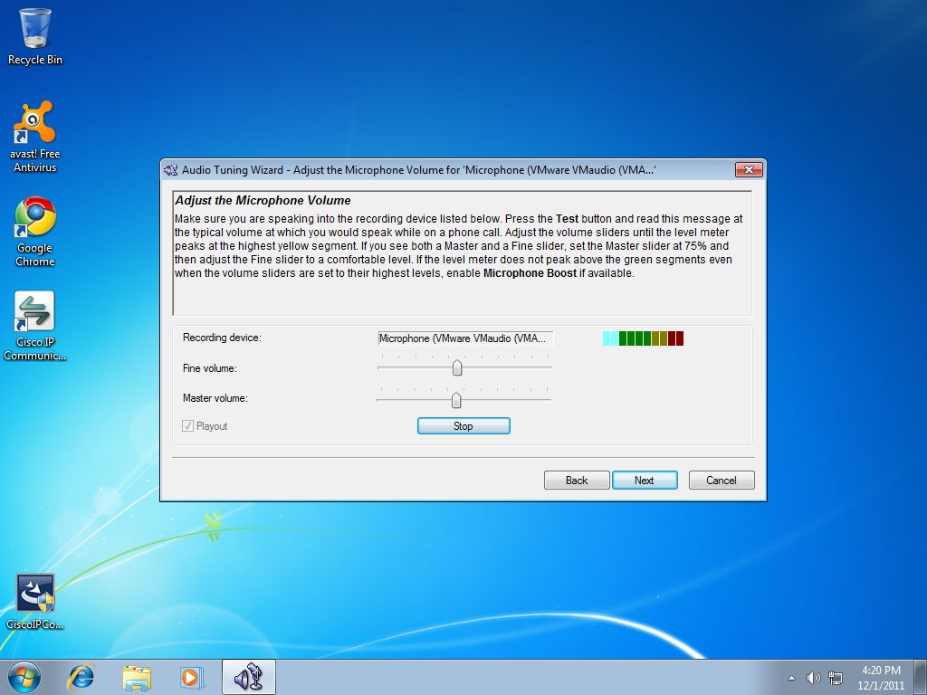
When we successfully configured network adapter bridging for hosted PC, next step is install and setup of cisco IP communicator:
When all is done, our testing home lab will look like this:
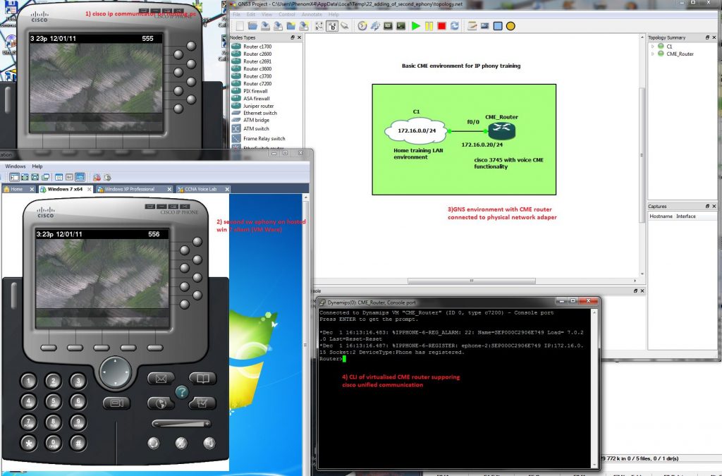
Ephone at top is installed in hosting PC with 172.16.0.10/24 IP, bottom ephone installed in hosted (virtualized) PC with 172.16.0.15/24 IP and GNS emulated cisco IOS with telephony service has its fa0/0 interface configured with ip 172.16.0.20/24 and acting as CME router (voice gateway).
Our first tested config (it will be explained in next articles) is
Now lets go for call placement from Office (bottom) ephone to Ciljak (me) top ephone:
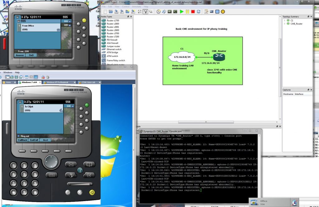
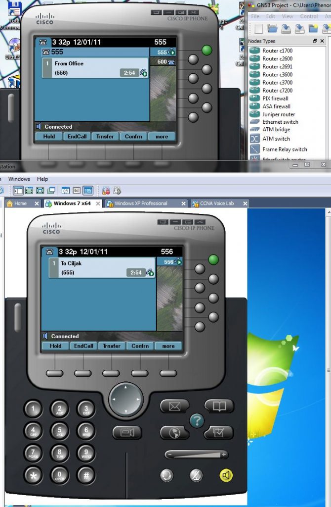
Closer look at phones during call processing is:
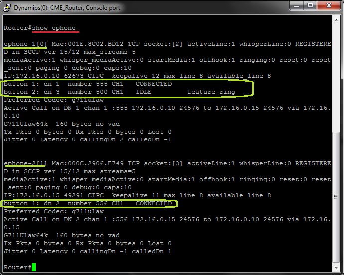
For obtaining info about ephones and ephone-dn to buttons (lines) of physical ephone use #show ephone CLI command:
