15. PPP and Frame relay in small network


PPP and Frame relay are protocols operating at data link layer used in segment of private WAN connection. PPP enable establish communication through serial link between cisco and noncisco device where can not be used proprietary HDLC cisco encapsulation. Frame relay networks offer packet switched technology in providers network. This article will focus on simple implementation of PPP serial link and Frame relay link in office environment.
About PPP (basics)
Is nonproprietary data link protocol carefully designed for compatibility with common HW devices. Enabled are these connection establishments:
- serial cables
- phone lines
- trunk lines
- cellular telephones
- fiber optic links
Extend features supported on serial links as quality management and PAP or CHAP authentication mechanism.
Main components of protocol are:
- HDLC protocol for encapsulation over point to point link
- Link control protocol – establish link connection
- Network control protocols (NCPs) – for establishing and configuration different network layer protocol
PPP configuration step by step
1) Enable PPP on interface
R #config t
R(config)#interface serial 0/0/0
R(config-if)#encapsulation ppp
2) Configure authentication
- PAP – older and unsecure, password is send as clear text
ppp authentication pap
ppp pap sent-username My_name password PSWD - CHAP – based on 3 way handshake mechanism using message digest – preferred if can be used
ppp authentication chap
3) Optionally configure compression with compress command
4) Optionally enable link quality monitoring
ppp quality 80 (1 to 100) – if link does not meet quality requirements then goes down
5) Optionally enable load balancing across link with ppp multilink
About Frame relay
All frame relay networks are build on 3 main components: DTE equipment at each end of connection (FRAD device of user), DCE (telephony company CO) and middle components (frame relay switches in operator network).
In frame relay networks our routers act as DTE devices and serial connection T1/E1 leased lines connect router to FR switch in POP (point of presence) our ISP (internet service provider). Frame relay switches on other end act as DCE devices.
DLCI – is local meaning number that identify link connection (but in opposite of IP address have only local meaning).
Frame relay address mapping is important for knowing how map which DLCI map to L3 address of remote destination. Mapping can be configured as dynamic or static. (for beginners is it a bit confusing in configuration and in CCNA eLearning materials). For configuration easier way is relay on dynamic mapping that use inverse arp. For static mapping must be used frame-relay map command.
Frame relay configuration step by step
1) Enable frame relay on interface
encapsulation frame-relay
and set encapsulation options cisco /ietf, cisco is on cisco devices default. IETF use only in multivendor environment when second end is non cisco device.
2) Configure bandwidth (does not affect real bandwidth) that is important for EIGRP and OSPF metric calculation
3) Set appropriateLMI type (cisco, q933a or ansi)
4) Optionally disable inverse arp for frame-relay DLCI mapping and configure appropriate static frame-relay map commands (important in end-to-end reachability in hub and spoke networks when spoke to spoke reachability is expected).
For training and hardening skills before CCNA examination we introduce next configuration scenario that can be as preconfigured downloaded from here.
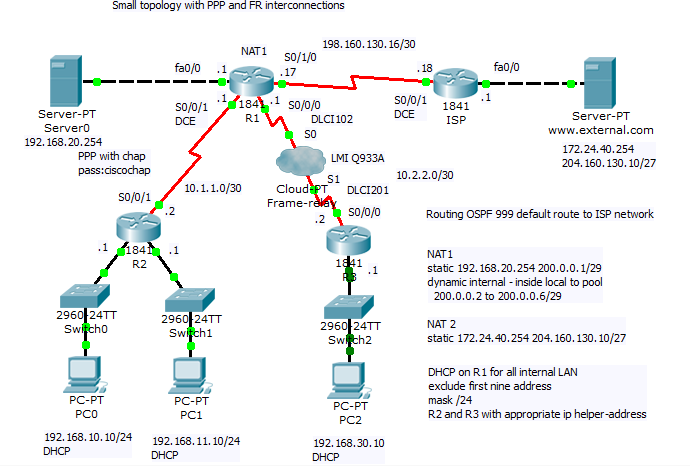
Scenario include PPP and frame relay configuration, subnetting and dynamic routing using OSPF routing protocol with ID 999. Office network use private addressing space with subnets 192.168.10.0/24, 192.168.11.0/24, 192.168.30.10 and 10.0.0.0/8 (10.1.1.0/30 and 10.2.2.0/30 VLSM subnets). On router R1 is configured NAT with PAT for private client address space and static nat translation for remote access to internal servers.
For PPP link configuration on R2 and R1 router we use
| username R1 password 0 ciscochap | username R2 password 0 ciscochap |
|
interface Serial0/0/1
ip address 10.1.1.2 255.255.255.252
encapsulation ppp
ppp authentication chap
|
interface Serial0/0/1
bandwidth 2048
ip address 10.1.1.1 255.255.255.252
encapsulation ppp
ppp authentication chap
ip nat inside
clock rate 2000000
|
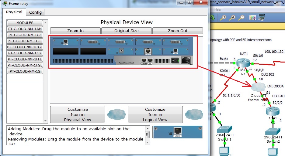
For Frame relay configuration at R1 FRAD and R3 FRAD we used (configuration of FR switch is beyond scope of our training but Packet Tracer offer Cloud-PT simulation object that we will introduce in one of our next article).
| R1 | R3 |
|
interface Serial0/0/0.102 point-to-point
ip address 10.2.2.1 255.255.255.252
frame-relay interface-dlci 102
ip nat inside
clock rate 2000000
|
interface Serial0/0/0.201 point-to-point
ip address 10.2.2.2 255.255.255.252
frame-relay interface-dlci 201
clock rate 2000000
|
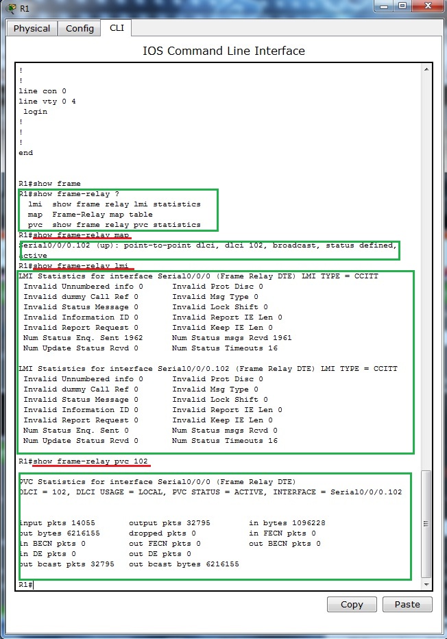
For examination of frame-relay open state and mapping remote address to local DLCI can be used this show commands:
- show frame-relay pvc
- show frame-relay map
- show frame-relay lmi
- show interface
Output from this commands show next pictures
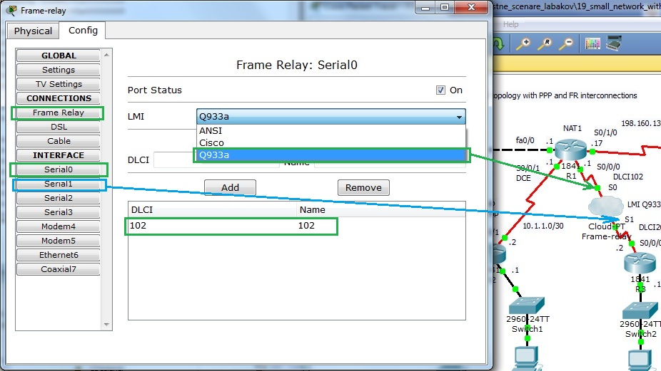
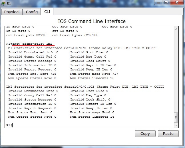
Output from show frame-relay lmi supply us with statistic information about link. LMI as management build in mechanism can be used for link state monitoring. As frame relay lmi standard can be selected cisco, q933a and ansi. As it is discussed in this topics http://www.tek-tips.com/viewthread.cfm?qid=402209, 21.3.2012 most important thing to consider is that both end must support apropriate type of LMI.
Output from show ip interface brief contain physical link and data link up state. If link state is down you need check clock rate command on DCE end of link, encapsulation command and authentication mechanism if used (optionally compression and other optional config).
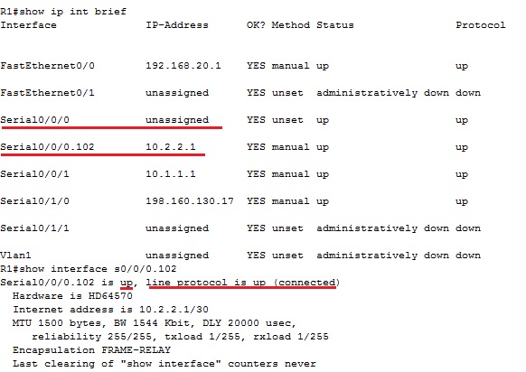
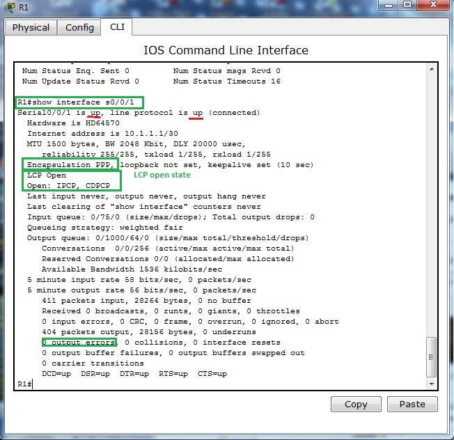
Next pictures show output from show interface on interfaces participating in PPP encapsulation. As you can see from output of command encapsulation is PPP and both LCP and appropriate NCP (IPCM and CDPCP) are in open state.
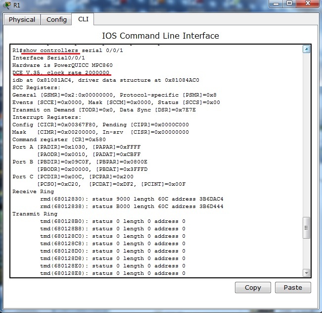
For further reference about connected serial cable and clocking of link you can use show controllers serial – interface s0/0/1 on R1 router act as DCE end with configured clock rate command.
Last two pictures show Frame-relay simulation device available in Cisco Packet tracer.