3D printing is additive technology for device prototyping. If you are interested in budget but very durable and affordable device i can recommand you printers by Joseph Prusa (homepage https://www.prusa3d.com/ ).
After successfull assembling you must gou through selftest of device. All axis callibration process and very crucial part of all good print is Z-axis calibration and when is necessary live Z- adjustment. All my mistakes are related to:
bad Z- axis calibration – to low or to high position of extruder nozzle
loosen gear feeding filament in extruder (inconsistent print)
innapropriate material for printedobjects (bad results if you use ABS for higher model and room temperature is not constant)
Quick introduction of most common problems and ho to suppress it are contained in next video
Virtualization – quick introduction
Virtualization is the creation of physically non-existent guest PC devices that can run on a single guest hardware system (guest) at the same time. On a server system having e.g. With 32 cores, 64GB RAM we can run several servers simultaneously, which in the past would form separate units (Active Directory, SMB, e-mail, DNS, authentication radius server,…).
Your question: Why should we go into this in our organization? As a rule, lower total costs for hardware, better spatial organization in the server room, after training the staff, everything for administration is available from one place. Virtual server disks are stored in the hypervisor as easily transferable files (as well as practically backupable).
Virtualization brings a number of benefits, but it also brings minor pitfalls that need to be kept in mind when designing a network topology that accommodates virtualization solutions:
+ positives are:
concentration of virtualized applications in one place
possibility of reallocation of system resources as needed between virtual PCs (reconfiguration of allocated RAM, number of cores, access to network interfaces)
flexible disk storage allocation (ability to access disks shared via iSCSI, eg via FreeNAS)
single centralized administration
easy backup of centralized virtual PC data with the possibility of their migration
– negatives are:
a bottleneck is created in terms of the failure of the guest HW virtual server (if in a non-updated environment the failure of one server allowed the running of other services, here the failure of the hardware will cause complete unavailability of services). The solution is to consider redundancy of at least some DNS / ActiveDirectory services
in commercial software, the virtual unit is equivalent to a physical one and has its own SID identifier
Running guest OS can take place:
In a virtual machine application environment (VMware Workstation or free alternative VirtualBox) – a solution suitable for training or consolidating older applications with newer ones. Scenario suitable if I want to ensure the running of the original CAD application in the new OS, where it would not otherwise work, I need to run an A3 scanner, which still works, but the manufacturer states the ruler only for windows XP, and so on. Note: this solution causes a large drop in performance – hw – host OS – application – hosted OS – application.
On the so-called level 1 (low-level) hypervisor – this is the most commonly modified Unix kernel providing a scheduler function that allows you to isolate a hosted OS in a virtual container environment (VMware ESXi server + Vcenter management center or XenServer maintained by Citrix and Citrix XenCenter – one of the application versions). The second mentioned solution is also available as a free alternative. The hypervisor has lower running system requirements and is involved in performance-critical enterprise virtualization solutions.
In addition to the VMware ESXi commercial solution, we also have a freely available solution for building a centralized virtual server in a small company environment, the most compatible form of which is also offered by Citrix – XenServer in the version without support and fees.
From the early years of www new technology will arisen. As fundamental building bocks of all web can be recongnized HTML and CSS.
HTML or Hypertext Markup Language is content descripting markup language for description of appropriate building blocks of all webpages. Today longterm supported version is 5.0. This version is meant to be open standard – new improvements are continualy added to its syntax.
For styling or visual theming is used CSS standard (standard for Cascade Style sheets). Actual verion is 3.0. HTML+CSS introduced separation of content and look of a pages. Content is more rigid bud external styles enable quick change of look of your page from one location on your webserver.
We can say that only HTML and CSS are main building blocks of all webpages but today webs are mor dynamic and adaptive. You can make administration from web backends, or you can make subscription and then gain access to elevated content of pages.
These improvements enable scripting technologies. These technologies can be divided on two main parts:
a) scripting technologies on server side – for a long time and beacause wide support in hosting houses wide spreaded technology is PHP. For PHP is common that generate pure HTML as interpreted output. Today standardized version is 7.4 but version 8.0 is in development. More reading about PHP can be found on https://www.php.net/docs.php or in more descriptive way on wiki https://en.wikipedia.org/wiki/PHP .
PHP is not only server side technology – for bigger projects but with lover support at hosting company are node.js (server side scripting with javascript), java jsp or servlets or microsoft asp.
b) scripting technology on client side – widely used is javascript (not confuse with java because this scripting languahe has nothing with java/ jsp as its name will sugest). Difference between server side and client side scripting is that client script must be downloaded to the browser and interpreted by them. Taht lead to possible problems with code confidentiality and posible blocking features on browser/ client side. Output of server scripting technology can by pure HTML/ CSS pages.
If you are involved in bigger projects or make common web for larger public existing frameworks will accelerate development. When you use framework you can obtain generated parts and use prepared parts of web. Most frameworks insist on design patterns named MVC (model – view – controller). MVC concept separate building parts of code in to:
model – driving logic of aplication, how are data handled and stored with database
view – visual part of aplication
controller – part handling requests from the clients and event generated by states of application
angular – used by google, big framewor for creation robust application, based on javascriptsyntax https://angular.io/docs
react – frontend development framwork used by facebook, based on javascript syntax (user friendlier as angular) https://reactjs.org/
jQuery – small framework for web scripting and DOM manipulation (separtaion of parts of page and manipuating them). Can be used for srooling menu creation, animation of galeries … .For furter reading you can visit https://jquery.com/ .
17. Port security on access layer switchport
Port security is feature that enable permit or deny traffic for end user PCs connected to access layer switch. Port security enable specify a group of valid MAC address on port. If maximum secure MAC address is reached then security violation modes lead to protect, restrict or shutdown of port.
There are 3 ways how to configure port security:
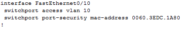
1) Static secure MAC addresses – manually configured with
switchport port-security mac-address MAC_ADDRESS
2) Dynamic secure MAC address – dynamic learned and stored only in address table (after restart cleared)
3) Sticky secure MAC address – mac address are learned dynamically and saved in running config (next can be merged with startup config).
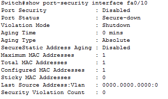
Default port security:
– disabled on port -> switchport port-security
– maximum nr. of secure MAC: 1
– violation mode: shutdown
– sticky address learning: disabled
Sample configs:
A) Dynamic port security configuration
s1#configure terminal
s1(C)# interface FastEthernet0 0/10
s1(c-if)#switchport mode access
s1(c-if)#switchport port-security
s1(c-if)#end
B) Sticky port security – can configure max. nr. of secure mac address, in this example we configure shutdown as the violation mode
s1#configure terminal
s1(C)# interface FastEthernet0 0/10
s1(c-if)#switchport mode access
s1(c-if)#switchport port-security (enable port security)
s1(c-if)#switchport port-security maximum 20 (maximum nr. of secure address)
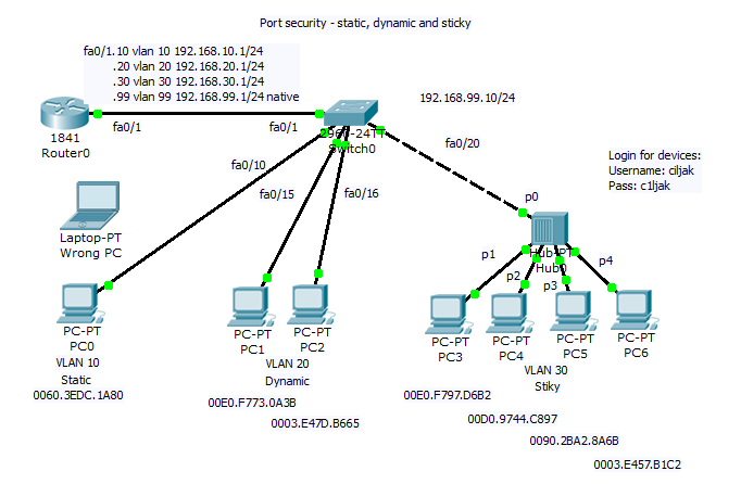
Network topology consist of router acting on stick and switch. Port security is configured sticky for 10 mac address for port 20 to 24 with commands:
interface FastEthernet0/20
switchport access vlan 30
switchport port-security maximum 10
switchport port-security mac-address sticky
!
interface FastEthernet0/21
switchport access vlan 30
switchport port-security maximum 10
switchport port-security mac-address sticky
!
interface FastEthernet0/22
switchport access vlan 30
switchport port-security maximum 10
switchport port-security mac-address sticky
!
interface FastEthernet0/23
switchport access vlan 30
switchport port-security maximum 10
switchport port-security mac-address sticky
!
interface FastEthernet0/24
switchport access vlan 30
switchport port-security maximum 10
switchport port-security mac-address sticky
You are strongly encouraged to try
1) Static port security for PC on vlan 10 on port fa0/10 with mac 0060.3EDC.1A80 – then disconnect device with mentioned mac and attach device with wrong mac (examine shuting down state of port), then correct port state and enable traffic forwarding.
2) Enable dynamic learning for PC on ports fa0/15 and fa0/16.
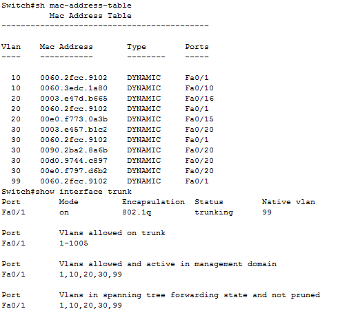
As example, output from show mac-address-table of switch
On port fa0/20 can be spot shared network segment (in our case it is hub interconnected segment).
16. Administrative Distance and route source preference
In environment with 2 or more enabled routing protocols must be present mechanism for selection of routing sources that are learned. What routing protocol obtained routes for remote network will be introduced to routers routing table? That is a big question.
Administrative Distance in short AD is considered parameter that will break the tie and say about trustworthiness of routing source.
Table of administrative distance of routing protocols
Routing source
AD
(administrative distance)
connected
0
static
1
EIGRP summary route
5
External BGP
20
Internal EIGRP
90
IGRP
100
OSPF
110
IS-IS
115
RIP
120
External EIGRP
170
Internal BGP
200
Say in other words – AD is number from interval <0, 255>. And lower is better that mean static route (AD=1) is preferred over OSPF learned route (AD=110).
Training scenario focus on introduction routing sources (learned route) from RIP, EIGRP and OSPF routing protocols.
Fully configured lab. scenario for Cisco Packet Tracer 5.2 or above can be obtained from here. Topology diagram show next picture.
Routing protocols configuration is
Router_A
Router_B
router eigrp 100
passive-interface FastEthernet0/0
passive-interface FastEthernet0/1
passive-interface FastEthernet1/0
network 172.16.5.0 0.0.0.63
network 10.1.1.0 0.0.0.3
auto-summary
!
router ospf 100
log-adjacency-changes
passive-interface FastEthernet0/0
passive-interface FastEthernet0/1
passive-interface FastEthernet1/0
network 172.16.5.0 0.0.0.63 area 0
network 10.1.1.0 0.0.0.3 area 0
!
router rip
version 2
passive-interface FastEthernet0/0
passive-interface FastEthernet0/1
passive-interface FastEthernet1/0
network 10.0.0.0
network 172.16.0.0
!
ip classless
router eigrp 100
passive-interface FastEthernet0/0
passive-interface FastEthernet0/1
passive-interface FastEthernet1/0
network 172.16.5.128 0.0.0.63
network 10.1.1.0 0.0.0.3
auto-summary
!
router ospf 100
log-adjacency-changes
passive-interface FastEthernet0/0
passive-interface FastEthernet0/1
passive-interface FastEthernet1/0
network 172.16.5.128 0.0.0.63 area 0
network 10.1.1.0 0.0.0.3 area 0
!
router rip
version 2
passive-interface FastEthernet0/0
passive-interface FastEthernet0/1
passive-interface FastEthernet1/0
network 10.0.0.0
network 172.16.0.0
!
ip classless
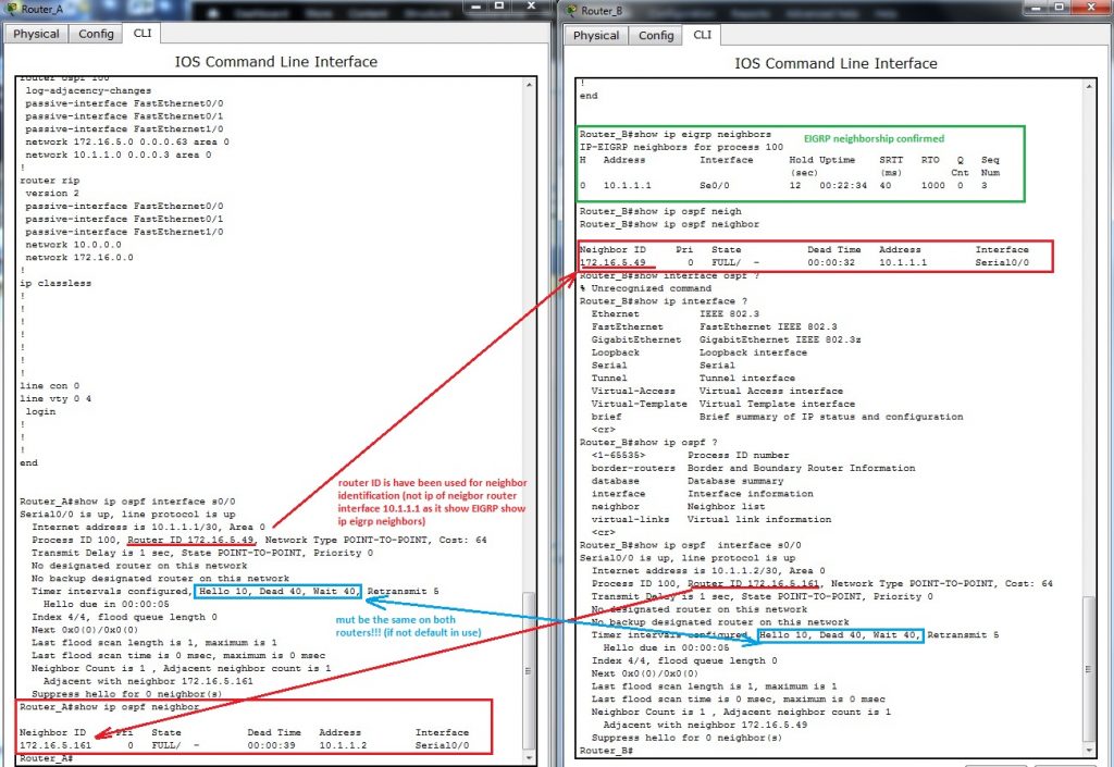
EIGRP and OSPF routing protocols will create neighborship relation between facing interfaces. This mechanism is important for generate triggers after breaking relationship after topology change in network and cause generating and spreading routing protocols PDU, algorithm recalculation and rearrangement in routing table.
If routing table is missing expected route please take a look at creation of neighbor relation and verify appropriate timers that trigger sending hallo packet or define time for detaching route from table after their potential error.
Important commands for troubleshooting at CCNA level are:
show ip eigrp neighbors
show ip ospf neighbor
show ip ospf interface INTERFACE
show ip route
show ip protocols
Output from neighborship verification commands are
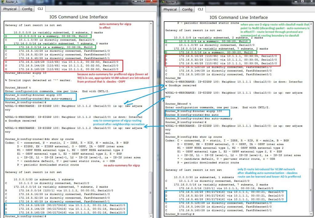
Now we can look at routing table both router A and B. What we can to expect? Which routing protocol introduce their route to routing table? Lower AD is preferred and lowest AD has EIGRP!
But what is wrong, routing table show only classfull D (Duall EIGRP route) that point nowhere (Null0)? Can you mentally answer why it is so? What is wrong in our config? Classless VLSM route (network mask is longer as appropriate classfull mask) are introduced by OSPF because OSPF is inherently classless routing protocol.
Please remember that null0 classfull route introduced to routing table by EIGRP protocol (leading D for that route) is because auto-summary was not suppressed and is in use. For correcting this behavior on our network we must type no auto-summary on router-config command prompt of router eigrp 100.
All that was we describe is recorded from output of CLI Router_A and Router_B on next picture.
———————-
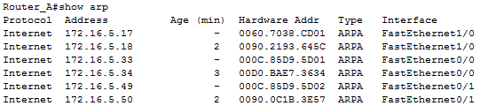
One of many processes that run on our router is mapping L3 address to L2 mac address on Ethernet interfaces. Info about learned relationship between L3 and L2 address offer ARP table of router. Their output can be visible after typing show arp on privileged exec of CLI (output depend on previews communication, arp cache is dynamic table that is aged after appropriate time non use of connection. That mean, if you will have all mac in table you must make ping sweep).
Records with character – in Age column is local interface of device. These records are excluded from aging mechanism! (- mean local interface on device, other are learned through ARP protocol)
15. PPP and Frame relay in small network
PPP and Frame relay are protocols operating at data link layer used in segment of private WAN connection. PPP enable establish communication through serial link between cisco and noncisco device where can not be used proprietary HDLC cisco encapsulation. Frame relay networks offer packet switched technology in providers network. This article will focus on simple implementation of PPP serial link and Frame relay link in office environment.
About PPP (basics)
Is nonproprietary data link protocol carefully designed for compatibility with common HW devices. Enabled are these connection establishments:
serial cables
phone lines
trunk lines
cellular telephones
fiber optic links
Extend features supported on serial links as quality management and PAP or CHAP authentication mechanism.
Main components of protocol are:
HDLC protocol for encapsulation over point to point link
Link control protocol – establish link connection
Network control protocols (NCPs) – for establishing and configuration different network layer protocol
PPP configuration step by step
1) Enable PPP on interface
R #config t
R(config)#interface serial 0/0/0
R(config-if)#encapsulation ppp
2) Configure authentication
PAP – older and unsecure, password is send as clear text ppp authentication pap ppp pap sent-username My_name password PSWD
CHAP – based on 3 way handshake mechanism using message digest – preferred if can be used ppp authentication chap
3) Optionally configure compression with compress command
4) Optionally enable link quality monitoring
ppp quality 80 (1 to 100) – if link does not meet quality requirements then goes down
5) Optionally enable load balancing across link with ppp multilink
About Frame relay
All frame relay networks are build on 3 main components: DTE equipment at each end of connection (FRAD device of user), DCE (telephony company CO) and middle components (frame relay switches in operator network).
In frame relay networks our routers act as DTE devices and serial connection T1/E1 leased lines connect router to FR switch in POP (point of presence) our ISP (internet service provider). Frame relay switches on other end act as DCE devices.
DLCI – is local meaning number that identify link connection (but in opposite of IP address have only local meaning).
Frame relay address mapping is important for knowing how map which DLCI map to L3 address of remote destination. Mapping can be configured as dynamic or static. (for beginners is it a bit confusing in configuration and in CCNA eLearning materials). For configuration easier way is relay on dynamic mapping that use inverse arp. For static mapping must be used frame-relay map command.
Frame relay configuration step by step
1) Enable frame relay on interface
encapsulation frame-relay
and set encapsulation options cisco /ietf, cisco is on cisco devices default. IETF use only in multivendor environment when second end is non cisco device.
2) Configure bandwidth (does not affect real bandwidth) that is important for EIGRP and OSPF metric calculation
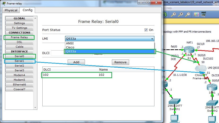
3) Set appropriateLMI type (cisco, q933a or ansi)
4) Optionally disable inverse arp for frame-relay DLCI mapping and configure appropriate static frame-relay map commands (important in end-to-end reachability in hub and spoke networks when spoke to spoke reachability is expected).
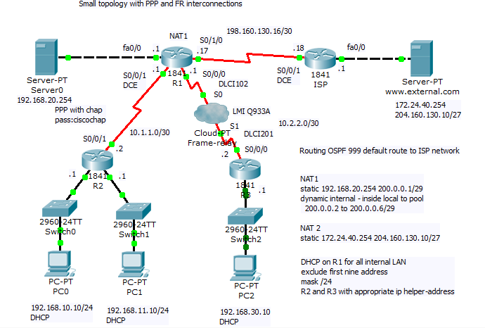
For training and hardening skills before CCNA examination we introduce next configuration scenario that can be as preconfigured downloaded from here.
Scenario include PPP and frame relay configuration, subnetting and dynamic routing using OSPF routing protocol with ID 999. Office network use private addressing space with subnets 192.168.10.0/24, 192.168.11.0/24, 192.168.30.10 and 10.0.0.0/8 (10.1.1.0/30 and 10.2.2.0/30 VLSM subnets). On router R1 is configured NAT with PAT for private client address space and static nat translation for remote access to internal servers.
For PPP link configuration on R2 and R1 router we use
username R1 password 0 ciscochap
username R2 password 0 ciscochap
interface Serial0/0/1
ip address 10.1.1.2 255.255.255.252
encapsulation ppp
ppp authentication chap
interface Serial0/0/1
bandwidth 2048
ip address 10.1.1.1 255.255.255.252
encapsulation ppp
ppp authentication chap
ip nat inside
clock rate 2000000
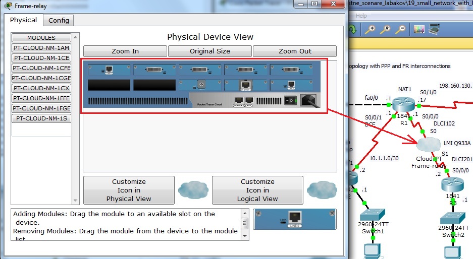
For Frame relay configuration at R1 FRAD and R3 FRAD we used (configuration of FR switch is beyond scope of our training but Packet Tracer offer Cloud-PT simulation object that we will introduce in one of our next article).
R1
R3
interface Serial0/0/0.102 point-to-point
ip address 10.2.2.1 255.255.255.252
frame-relay interface-dlci 102
ip nat inside
clock rate 2000000
interface Serial0/0/0.201 point-to-point
ip address 10.2.2.2 255.255.255.252
frame-relay interface-dlci 201
clock rate 2000000
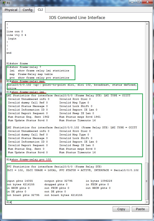
For examination of frame-relay open state and mapping remote address to local DLCI can be used this show commands:
show frame-relay pvc
show frame-relay map
show frame-relay lmi
show interface
Output from this commands show next pictures
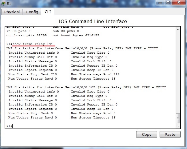
Output from show frame-relay lmi supply us with statistic information about link. LMI as management build in mechanism can be used for link state monitoring. As frame relay lmi standard can be selected cisco, q933a and ansi. As it is discussed in this topics http://www.tek-tips.com/viewthread.cfm?qid=402209, 21.3.2012 most important thing to consider is that both end must support apropriate type of LMI.
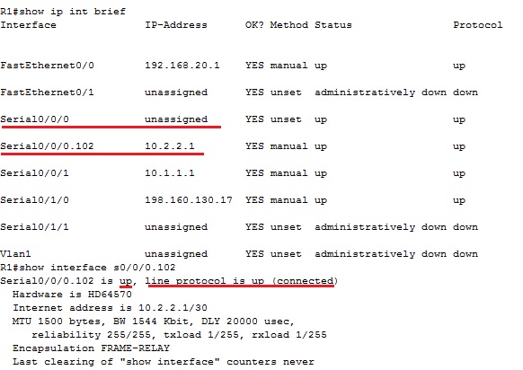
Output from show ip interface brief contain physical link and data link up state. If link state is down you need check clock rate command on DCE end of link, encapsulation command and authentication mechanism if used (optionally compression and other optional config).
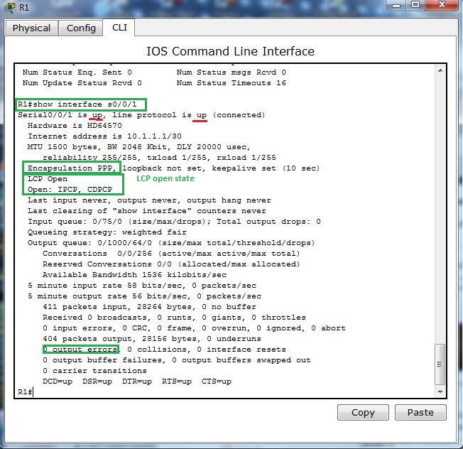
Next pictures show output from show interface on interfaces participating in PPP encapsulation. As you can see from output of command encapsulation is PPP and both LCP and appropriate NCP (IPCM and CDPCP) are in open state.
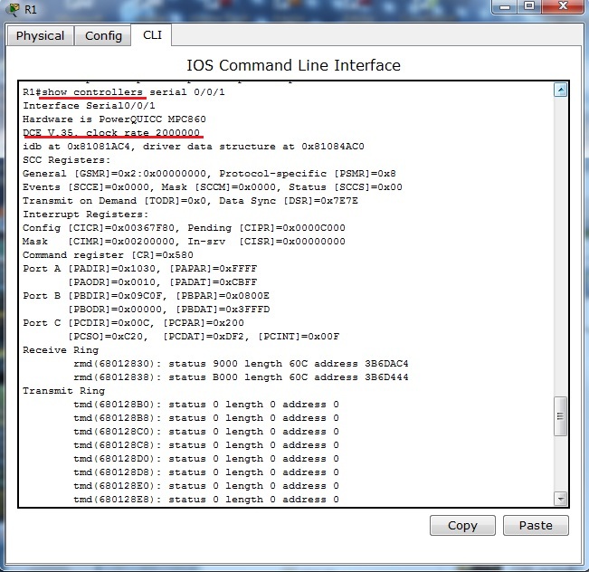
For further reference about connected serial cable and clocking of link you can use show controllers serial – interface s0/0/1 on R1 router act as DCE end with configured clock rate command.
Last two pictures show Frame-relay simulation device available in Cisco Packet tracer.
14. Wrong default route propagation in OSPF enabled network
Default route introduce ultimate outgoing interface for L3 PDU from our network. Most common use is in stub-networks where is only one interface pointing to outside network (in this case is no need for load balancing between two or among ISPs interfaces). Instead of routers having to store routes for all of the networks in the internet, they can share a single default route to represent any network that is not in the routing table.
In small office networks is static routing and manual default route settings in use but in large network or in much more flexible network scenarios are dynamic routing protocol introduced.
Static default route can be propagated from router where command ip route 0.0.0.0 0.0.0.0 interface/IP_of_next_hop to all other routers in network.
How to enable default route distribution to network with most common IPv4 routing protocols?
1) Configure static default route on router that act as network boundary to ISP network with command: ip route 0.0.0.0 0.0.0.0 interface/IP_of_next_hop
2) Default static route needs to be advertised to all others routers that use dynamic routing protocols
for RIP1/2 use router command: default-information originate
for EIGRP use router command: redistribute static
for OSPF use router command: default-information originate
But what is happen when wrong default route is introduced in network topology? How troubleshoot problem with wrong default static route? We going to explore how this condition affect our production network and how to fix it.
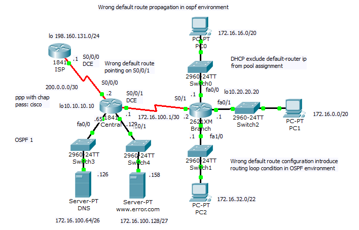
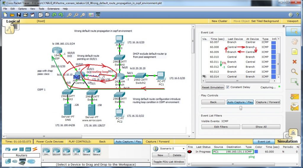
Preconfigured scenario in cisco packet tracer 5.2 or above can be obtained from here. Small office network in this scenario look like this
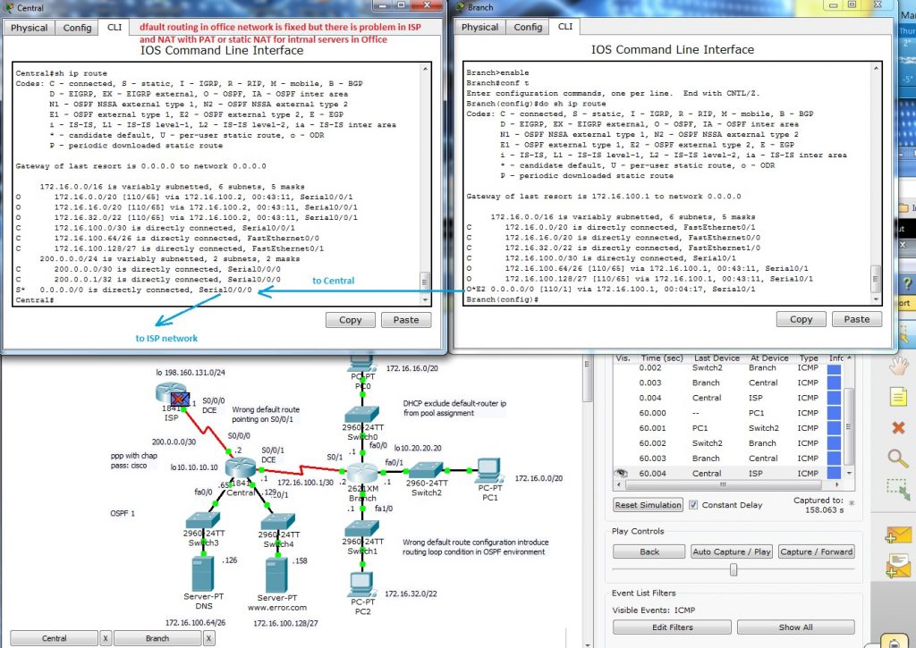
Network topology consist of central router (act as boundary between office network and WAN) and one branch router (for simplicity is there only one branch router). All end devices are on separate networks and private address space is in use in internal network. Wrong default route
ip route 0.0.0.0 0.0.0.0 serial0/0/1 (correct it is serial0/0/0) introduce in network routing loop that we will examine.
Our lab include option for sending ping and follow what is happen. Toggle to simulation mode and Auto capture/play.
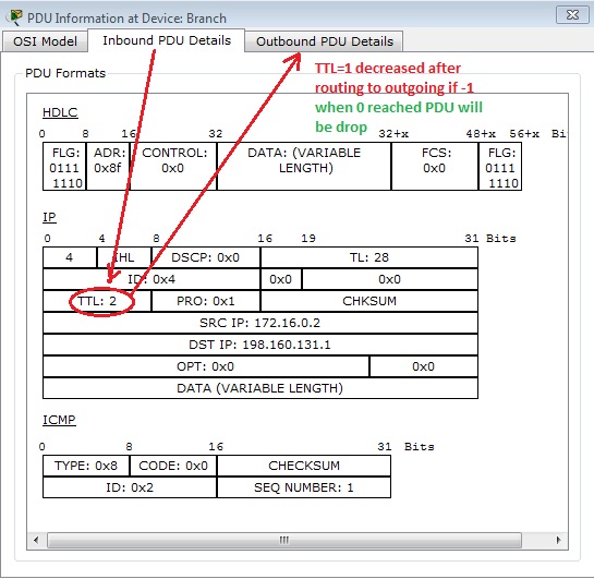
Wrong default route lead PDU to its origin and Branch router loop back to central router with default route. L3 PDU contain mechanism how to break endless looping of PDU – TTL in data packet header is decreased after L3 routing to appropriate interface as you can see on next picture (PDU examination in cisco packet tracer – simulation mode).
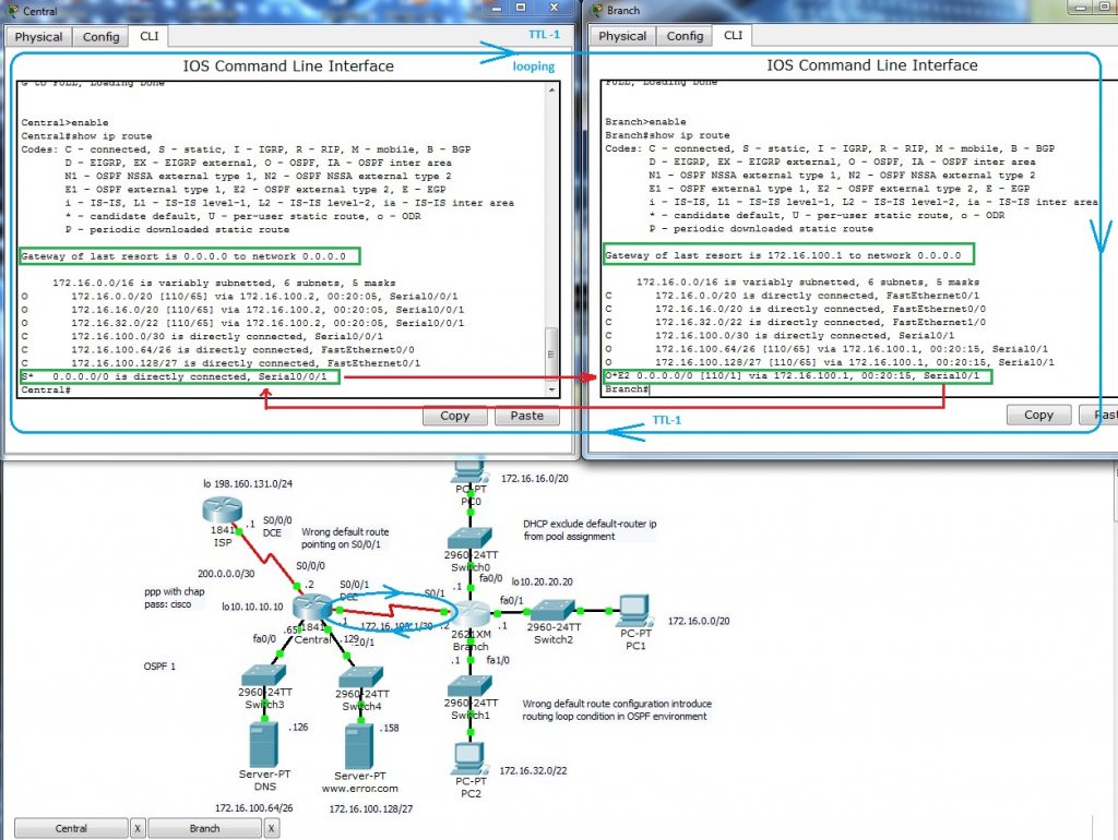
Output from most common troubleshooting command show ip route that output from routers routing table issued on both routers is:
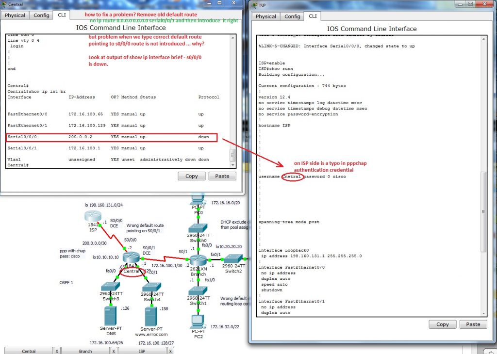
Now is time correct our mistake. What we need to do? At first you must remove wrong default route. There is no way how to change existing static route. First remove wrong route with command
no ip route 0.0.0.0 0.0.0.0 serial0/0/1
that point not to ISP router but back to internal Branch router and cause routing loop. Next step is introduce appropriate (correct) default route this way:
ip route 0.0.0.0 0.0.0.0 serial0/0/0
and now we going to examine output from show ip route. But you will obtain problem that is cause of my mistake. In routing table is not default route introduced. Keep in mind that static route (but all routes) is in output only when appropriate outgoing interface is on. Then we will examine up state of s0/0/0 interface. As you can see physical layer is Up but protocol is down.
S0/0/0 interface on Central router is connected to ISP with PPP link that use chap as authentication protocol. We need examine clock command on DCE end of serial link and then authentication credential on bot end of link.
And there is the problem, ISP side is supplied wit incorrect name of Central router. there is a typo Cnetral and correct it may state Central.
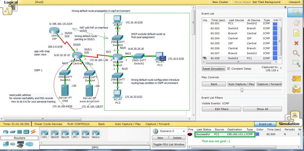
Default route is now correct but can we establish a connection between end devices on office network and ISP? Fire ICMP packet to destination nework 198.160.131.1. Packet can reach ISP router but then is discarded because no translation to public network have not been made. We are closer to our goal, data re well routed but address translation on private network boundary must be established.
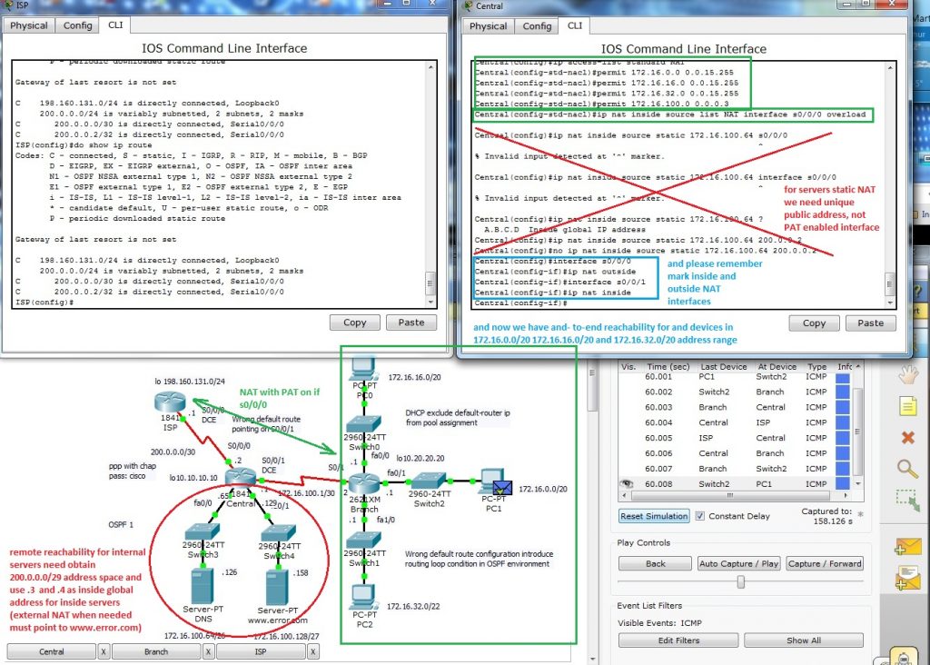
For ISP (internet access – now without security configuration) connection in network with many clients I decided for NAT (network address translation) with PAT (port address translation) on interface s0/0/0.
At first we must create standard access list (i use named but also can be used numbered)
ip access-list standard NAT
permit 172.16.0.0 0.0.15.255
permit 172.16.16.0 0.0.15.255
permit 172.16.32.0 0.0.15.255
permit 172.16.100.0 0.0.0.3
and then enable nat translation with command
ip nat inside source list NAT interface s0/0/0 overload
most common beginners (also me) mistake is forget mark appropriate interface as ip nat inside and outside. in our case it is:
interface s0/0/0
ip nat outside
interface s0/0/1
ip nat inside.
Now we can place simple PDU between appropriate ends.
As „how to?“ training you can establish connection for inside servers and enable reach them from ISP side. There must be used static nat and address range for inside global must increase from 200.0.0.0/30 to minimal 200.0.0.0/29 as it state previews picture.
For port roles selection is important which switch is selected as root bridge. That mean after root bridge selection process (in fact during this process) are port roles determined. (we will discus 802.1d STP, difference in 802.1w rapid STP will be explicit marked in document).
In stable converged L2 topology with STP support are there these types of ports:
Root ports – exist on non- root bridges and are switch ports with best cost path to root bridge.
Designated ports – exist on root and non-root bridges. For root bridge all ports are designated ports!!! (quick examination but there can be confusion if root-bridge role is distributed among VLANs or when there is default VLAN root bridge selected with other mechanism as other VLANs). Please keep in mind that on segment is allowed only one designated port!!!. Designate ports also as root ports are capable populate mac-address-table (CAM table of switch).
Non-designated ports – switchport that is blocked (in 802.1W rapid STP is used term alternate ports in discarding state).
Disabled port – is administratively down (has no function or does not participate in STP).
STA (spanning tree algorithm) determines which port role is assigned to each switchport:
switch port with lowest overall path cost to root bridge is root port
in network topology all switches except root bridge have a single root port
if 2 ports have same port cost – switches uses customizable port priority value or lowest port ID if both port priority value are same (if cost is same – > lowest port ID – >if equal port ID break the tie, that mean Fa0/1 < Fa0/2 < Fa0/3 …. As example port fa0/0 default priority is 128.1 configurable_priority.portID). As configurable priority can be used number from 0 to 240 with increment 16, and lower priority is better/ preferred.
Switch with lowest bridge priority (if equal lowest MAC address) is selected as root bridge.
Root bridge set all its port as designated (in stable topology are in forwarding state).
Other, non-root bridge switches set one port with lowest cost to root-bridge as root ports.
In shared segment are determined port roles way that set one port as designated per shared segment and all other set as non-designated (prevent L2 loops and broadcast storm arisen). Keep in mind that lowest priority is first, only if equal then port priority or portID is used for tie breaking!!!
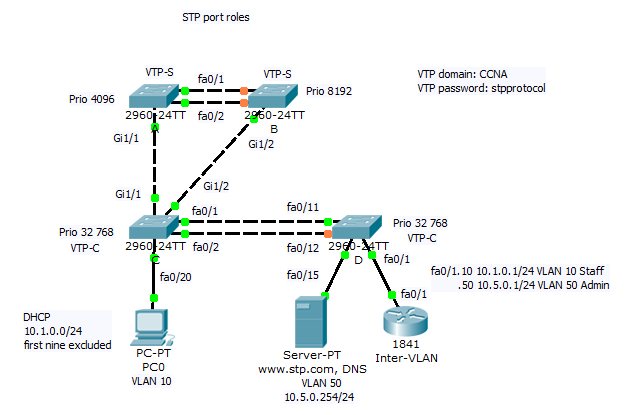
When we repeat basic theory, now we can prepare our PKT simulation lab. Preconfigured scenario in Cisco Packet Tracer 5.2 or above can be obtained from here.
Scenario consist of 4 switches. Root bridge role is determined by spanning-tree vlan 1, 10, 50 priority 4096 command for switch A. For VLAN information consistency is used proprietary VTP protocol with VTP domain: CCNA and password: stpprotocol. For redundancy of server roles in VTP two switches A and B are configured as VTP servers. Inter VLAN communication establish router on a stick Inter-VLAN.
Staff PCs are on VLAN 10 and office web and DNS server is on VLAN 50 and use IP address 10.5.0.254/24.
Host Staff PCs obtain address automatically by DHCP that exclude first nine IP address from address pool.
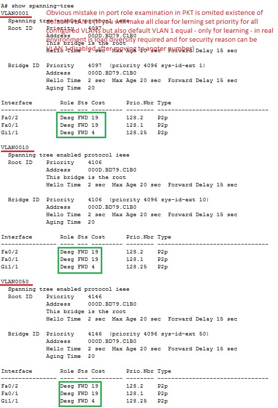
As it was mentioned earlier root bridge can be noticed by two way from show spanning-tree command – explicit marking themselves as root bridge: „This bridge is root bridge“. Second way how to examine root bridge from output of show spanning-tree command is by fact that all port of root bride are set as designated. Next picture show output from switch A
Now we will take closer look on port role selection in training environment
Process that lead to convergence in L2 topology is:
Root bridge was elected because their lowest spaning-tree vlan 1, 10, 50 priority 4096
Root bridge mark all its port as designated for all VLAN for which is root bridge (for simplicity our lab set root bridge role for all VLAN the same)
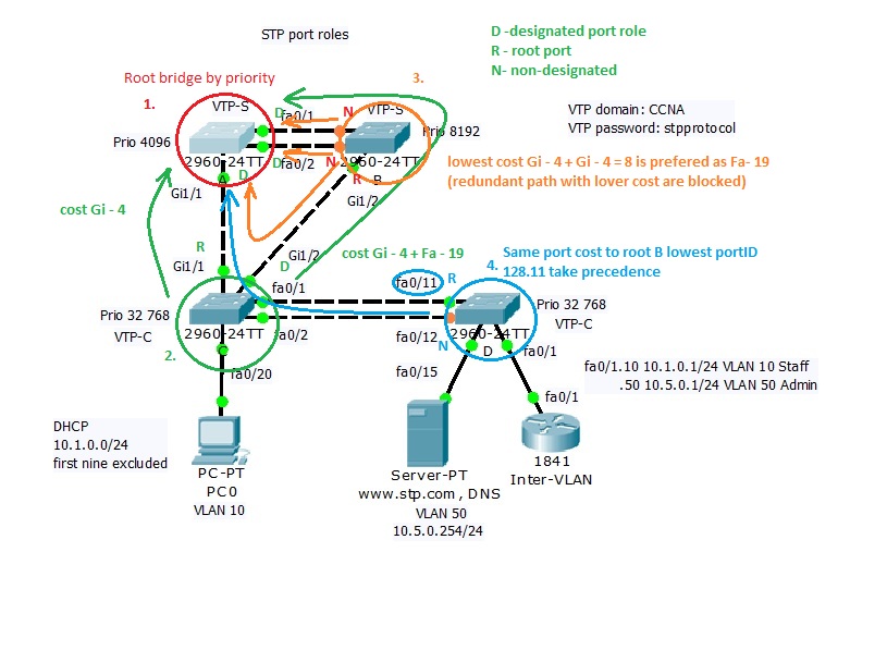
Election of root ports on all non root bridge switches select root ports. Root ports has lowest cost to rood bridge and only one root port per switch is selected. For switch marked with nr. 2 (green) is lowest cost port Gi1/1 because port cost is 4 (Gi1/1 cost), Gi1/2 has cost (4+19 Fa of orange switch B). For orange switch with nr. 3 is as root port selected port Gi1/2 because its cost to root bridge is 8 ( 4 Gi + 4second gigabit link from green to red switch) that is lower than 19 and 19 (costs of fa0/1 and fa0/2 ports). Blue switch with nr. 4 has two equal path cost (blue arrow in picture). If port cost are equal then port priority configured by user or port ID (128.11 and 128.12 – only port ID are different if configurable port priority is default 128 as in our case). Lower portID 11 (port 11 – 128.11) determine role of root port. Now we know which ports are designated on root bridge (all) and which are root ports on all non- root bridge.
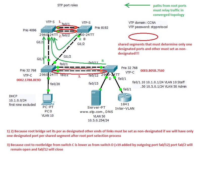
Elect designated and non-designated ports per segment. Each segment can have only one designated port, other is non-designated (prevent L2 loop creation). Next picture mark shared segment where must be selected designated and non designated role. Keep in mind that path from root ports with lowest cost to rood bridge must be open. Now we must examine only segment that does not participate in forwarding data from root ports to root-bridge (are not best path to root bridge). Final step that lead to converged L2 topology is on next picture
CUCM configuration for call hunt is more flexible and robust. During creation of hunt environment we going through this steps:
Create line groups that contain hunted extensions (in our case 1000, 1001, and 1002)
Create hunt lists that contain line group or groups
Finally create and adjust hunt pilot
In this lab our goal will be create config that support this scenario.
Now we going to create line groups that specify hunting behavior – Line groups are added to hunt lists which select order during hunting through line groups. Finally associate hunt pilot to appropriate hunt list.
I) Line groups
create DNs for phones and associate them
in CM administration Call Routing>Route/Hunt>Line Group and add new
specify RNA (ring no answer) – time of each DN in line group will ring before no answer is reached and call is relayed to next DN in group
distribute algorithm: Top Down – each new call starts at the top of list, Circular – round robin fashion – new call starts at the next DN after previous used on call, Broadcast – all DNs ring simultaneously or Longest idle (number that was longest in On Hook state become ringing)
Hunt – options for call state (Busy, noan …), determine moving of call through line groups if they exist (our simple scenario has only one line group)
add DNs to line group (1000, 1001 and 1002) and save
After successful configuration new entry in line group list exist
II) Hunt list
go to Call Routing>Route/Hunt>Hunt list and add new
fill name and select CUCM group if it is not stand alone CUCM deployment as in our case – then save
in hunt list configuration – add line groups (line groups are top down processed please remember this fact – order in list is important) and save
III) Hunt pilot
Call Routing>Route/Hunt>Hunt pilot and add
specify hunt pilot number (3000 in our case)
select hunt list or lists
set Alerting name (displays on phones receiving calls by dialing hunt pilot number)
optionally set hunt forwarding (for our examination we first leave this field blank)
Our lab is configured to support call hunt on pilot number 3000. It is time to try our config. From phone with extension 1002 initiate call to hunt pilot nr. 3000. Cal is routed to first number 1000 in circular fashion (circular distribution algorithm). After 20s configured as no answer interval our phone receive ringing after next 20s. Caller phone receive noanswer signal because no forward option was configured.
Finally we adjust no answer forwarding in hunt pilot configuration menu.
Now is call processing handled so as it is described in firs picture with configuration goals. When any of extensions in line group does did not noanswer call is forwarding to its final destination number 2000 (it is a shared line in our training environment).
15. Extension mobility in CUCM v. 8.6
Extension mobility (EM) enable user log in to any phone in working environment and then obtain appropriate private configuration of their phone. This functionality is ideal in environments with moving workers.
EM is a phone service that must be enabled and apply user-specific device profile. But separate device profile must be made for all type of supported devices (7965 phone has 6 button but 7940 only two that must be properly accommodated).
Administrator has these options for logging behavior:
allow multiple logins – multiple logged in phone
deny login – when logged in one phone another reply with error until logout previews
auto-logout – only one logged in device in a time
How to enable EM in CUCM?
1) Activate cisco EM service. In serviceability web page – Tools>Service activation and select Cisco Extension mobility and Save.
2) Configure EM service parameters. In CUCM administration page go to: System>Service parameters and select appropriate server (our scenario is single server). Select Cisco extension mobility service from service drop-down.
Scroll to Clusterwide Parameters (force logout after maximum login time has expired, and timer number, login behavior.) Also numeric ID for user can be enabled or enable remember of last logged in user.
3) Add the EM service. Go to Device > Device settings > Phone services and add new. Give service appropriate name (EM_service) and to service field type: http://<IP_address_of_Publisher>:8080/emapp/EMAppServlet?device=#DEVICENAME#.
Make sure Enable is checked and optionally check Enterprise subscription (automatically subscribes all IP phones to EM service).
4) Create default device profile. In CUCM administration page go to Device > Device settings > Default device profile and add new. Select Product type (phone model we only have CIPC phones) and Device Protocol.
5) Create Device Profiles. Go to Device > Device settings > Device Profile and add new. Select phone model for particular user phone and enter name for that profile. Configure user specific settings: DN, Button and other parameters.
6) Subscribe Device profiles to the EM service. From Device Profile page choose Subscribe/Unsubscribe Services from links and click go. Chose EM service added previews and Next. Enter display name for EM service and ASCII version for phones with low resolution display. Click Subscribe and Save. Remember subscribe both Device profiles and IP Phones to EM service – user will be unable log out after he log in and device profile is applied.
7) Associate Users with device profiles. Go to User Management > End User Select user whom you want create profile associations or create new user. For user chose Device Profiles that should be associated to user (if more profiles selected one must be selected to use after logging into EM).
8) Enable EM for Phones. Go to Device > Phone and select appropriate phone which will serve for EM. In Extension Mobility selection check enable extension mobility box. Chose specific Device profile or currently configured device setting as in Log Out Profile. (log Out profile is configuration that is applied to phone when no-one is logged in. Often it is emergency or local capabilities.)
9) Subscribe Phones to EM service. In phone configuration page, choose Subscribe/ Unsubscribe Services. Chose EM service from Service pull-down. Enter the name that will appear on IP Phone.