Call forward is a voice productivity feature that can to direct all of your calls to different ephone.
There are 2 different types of call forward:
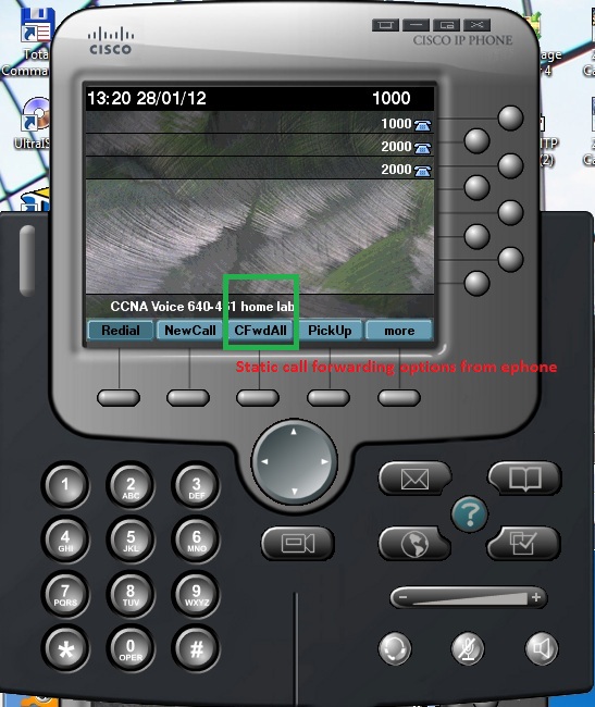
1) Dynamic call forwarding – forward calls on the cisco phone itself.
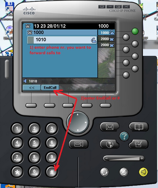
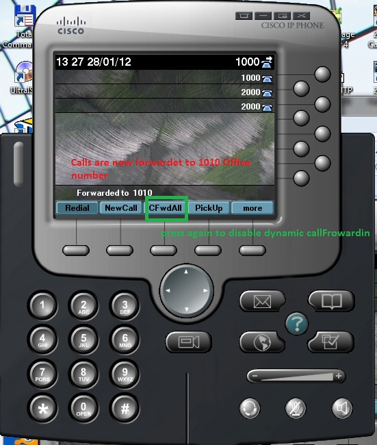
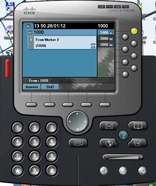
To forward call you can press CFwdAll softkey on ephone, enter the phone number you want forward a calls to and press End softkey or # button. This step by step process show next pictures.
You can see icon in upper-right corner to indicate that phone has been forwarded.
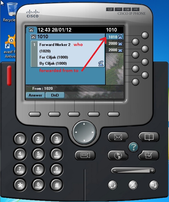
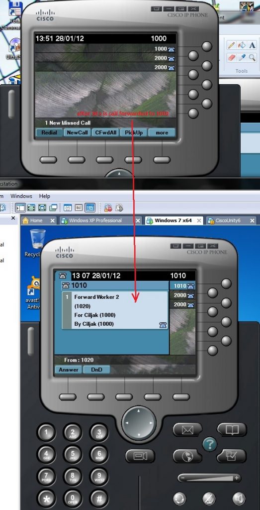
When forwarded call is received by appropriate device on their screen show message: call to number 1000 Ciljak from 1020 was forward to Worker 2 (1010).
When we will stop phone to forwarding calls, press the CFwdALL softkey again.
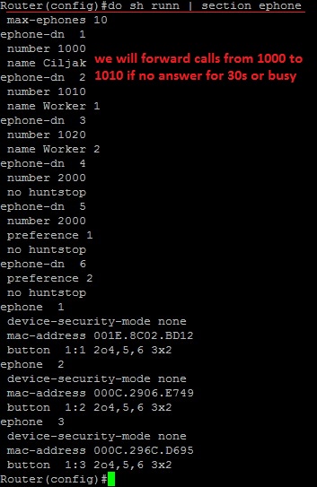
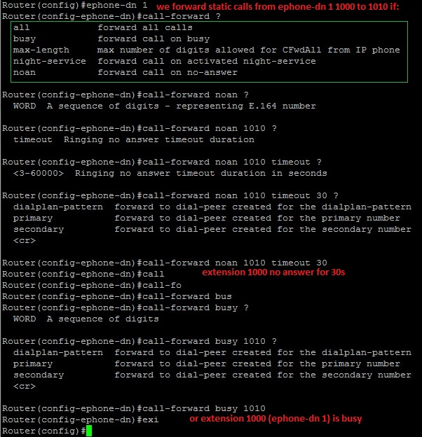
2) Static call forwarding – configure forwarding within cisco IOS. These are more options that offer dynamic call forwarding method. There are these options that can be configured at ephone-DN.
all – forward all incoming call
busy – forward calls when phone is busy
night-service – forward calls when CME is in night-service active time mode
noan – forward calls after a specified amount of time when phone has not been answered
Closer look at noan and busy call forwarding show next pictures:
Now we look at no answering ephone 1 with extension 1000 that will be forwarding to 1010 after 30s timeout of no answering.
5. Hybrid phone system for helpdesk environment
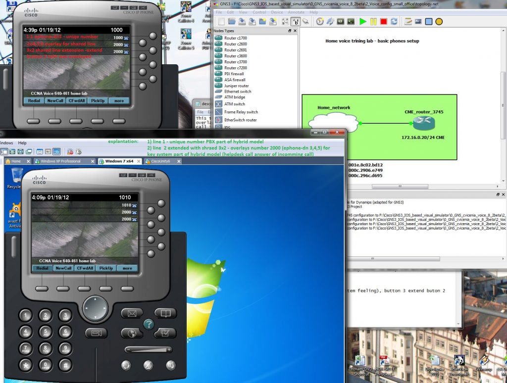
This training environment will introduce network helpdesk office. 3 ephones are configured with unique numbers but also with overlay button and third button is used for overlay line extension (x button). Each ephone can in future answer a call incoming from PSTN (call of clients calling to helpdesk).
ephone-dn 1
number 1000
name Ciljak
ephone-dn 2
number 1010
name Worker 2
no huntstop
ephone-dn 3
number 1020
these number are individual
ephone-dn 4
number 2000
no huntstop
priority 0
ephone-dn 5
number 2000
no huntstop
priority 1
ephone-dn 6
number 2000
no huntstop
priority 2
ephone-dn 4 to 6 introduce shared line feeling and overlay assignment enable equal response from all phones with ability answer call from other phones when any other is busy (in active call).
ephone 1
mac xxxx.xxxx.xxxx
button 1:1 2o4,5,6 3×2
button 1 individual dn, button 2 is overlay (key system feeling), button 3 extend button 2 overlay line.
Configured ephones will look like this
4. Extended watch line scenario
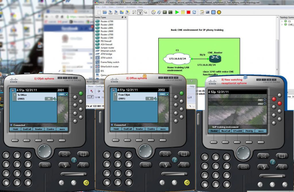
New scenario will extend previews with new ephone. Now we have three ephones. Our lab consist of:
1 ) Ephone 1 – extension 2001 – name Ciljak – IP 172.16.0.10/24 on hosting pc
2 ) Ephone 2 – extension 2002 – Name Office – IP 172.16.0.15/24 hosted on win 7 virtual PC
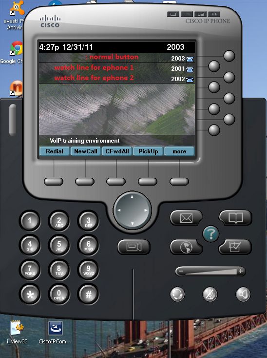
3 ) Ephone 3 (new) – extension 2003 and two watch line monitoring activity on ephone 1 and 2 (can act as receptionist ephone) IP 172.16.0.16/24.
Our goal is ephone-dn assignment to phone buttons as it is on next picture
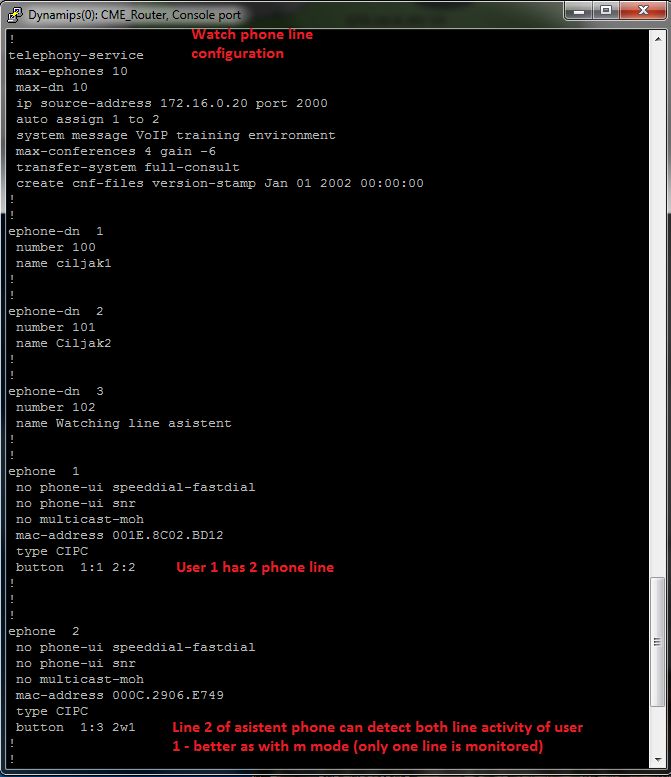
CME was configured with these commands:
ephone-dn 1
number 2001
name Ciljak
!
!
ephone-dn 2
number 2002
name Office
!
!
ephone-dn 3
number 2003
!
!
ephone 1
mac-address 001E.8C02.BD12
type CIPC
button 1:1
!
!
!
ephone 2
mac-address 000C.2906.E749
button 1:2
!
!
!
ephone 3
mac-address 000C.296C.D695
type CIPC
button 1:3 2w1 3w2
Commands introducing new ephone in this testing lab are marked with green color.
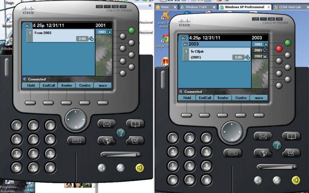
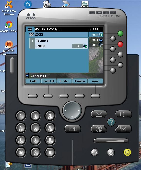
Watching ephone 3 detect activity on ephone 1
also as activity on ephone 2 (office) on their third line
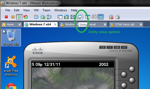
VMware workstation offer for us unity view of application running in hosted environment. This options you can enable activating tool button marked next
When we „set free“ GUI of IP communicators then our lab will be much interesting
3. Monitor and watch line button separator
Monitor (m) separator allows receptionist or assistant phone to monitor your ephone-dn and examine your currently calls. Receptionist can optionally take care about your call and take message for you.
Example of config is:
cme(config)#ephone-dn 1
cme(config-ephone-dn)#number 2001
cme(config-ephone-dn)#ephone-dn 2
cme(config-ephone-dn)#number 2002
cme(config-ephone-dn)#exit
cme(config)#ephone 1
cme(config-ephone)#button 1:1
cme(config-ephone)#ephone 2
cme(config-ephone)#button 1:2 2m1 – line 2 on receptionist ephone monitor activity of ephone-dn 1
cme(config-ephone)# end
Possible problem will arise when there is 2 or more ephone-dn configured on monitored ephone. Then you need configure multiple monitor button on monitoring receptionist ephone.
Possible and preferred solution is configure watch phone (w) button options that does same thing with exception that it monitors all the ephone-dn instead of just one (m – mode).
Implementation of watch line feature for phone line in our testing environment:
1) Configuration commands
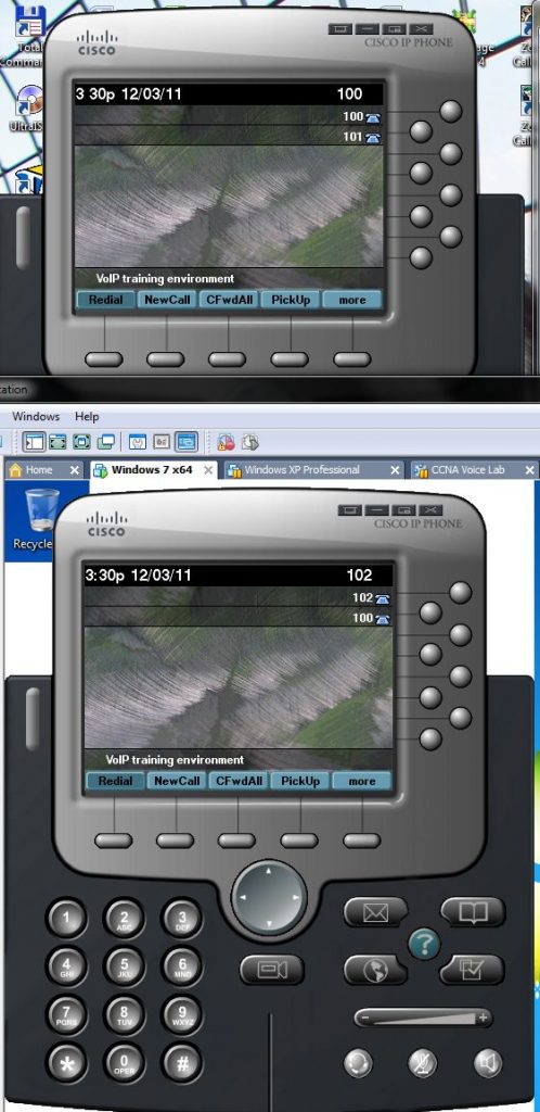
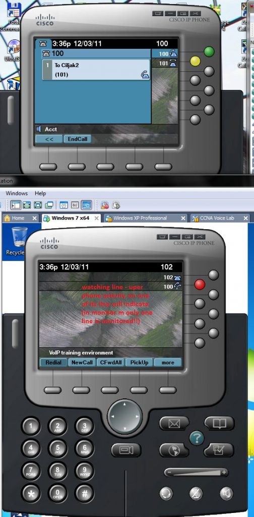
2) Look at prepared ephones in idle state
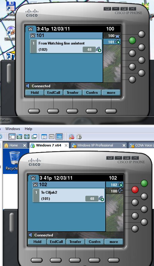
3) Watch line activity during call on upper ephone (watch line is second line on bottom ephone that monitor upper ephone line active – call to 101 or 100 number)
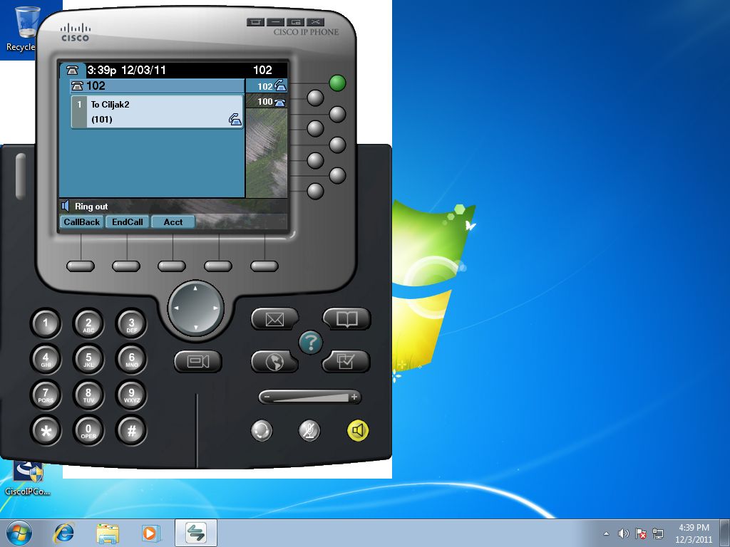
Call to 101 Ciljak 2 ephone-dn on upper ephone
2. Ephone button options
Button ephone-config commands are used to assign ephone-DNs to specific ephone.Button separator are used between line number (appropriate telephony line) and ephony-DN.
Example of config ephone 1 for normal beep:
router(config) # ephone-dn 1
router(config-ephone-dn) #number 2001
…
router(config) # ephone 1
router(config-ephone) # button 1:1
router(config-ephone) #end
Lets look at configurable button separators:
: – normal phone line
s – silent ring, ringer muted, call waiting beep muted
b – silent ring, ringer muted, call waiting beep not muted
f – feature ring
m – monitor line, silent ring, call waiting display suppressed
w – watch line, watch the phone off-hook via the phones primary ephone-dn
o – overlay lines, combine multiple lines per physical button
c – overlay call-waiting, combine multiple lines per physical button
x – expansion/ overflow, define additional expansion lines that are used when the primary line for an overlay button is occupied by an active call
For each button can be used different separator
button 1f2 2s3 3o5,5 …
Our next article will focus on watch line configuration, that will expand m – monitor mode (only one monitored line, but not all ephone-dn in use). This feature is used on receptionist phones to see if an employee is using the ephone.
1. Basic VoIP lab with two ephone for upcoming experiments
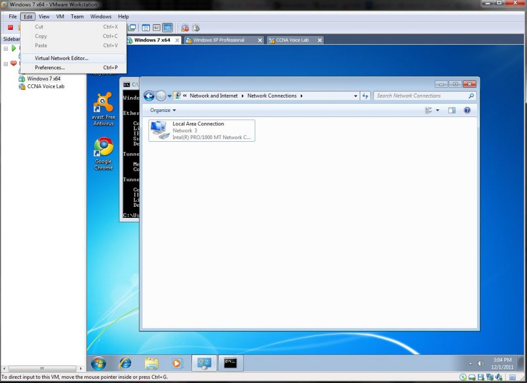
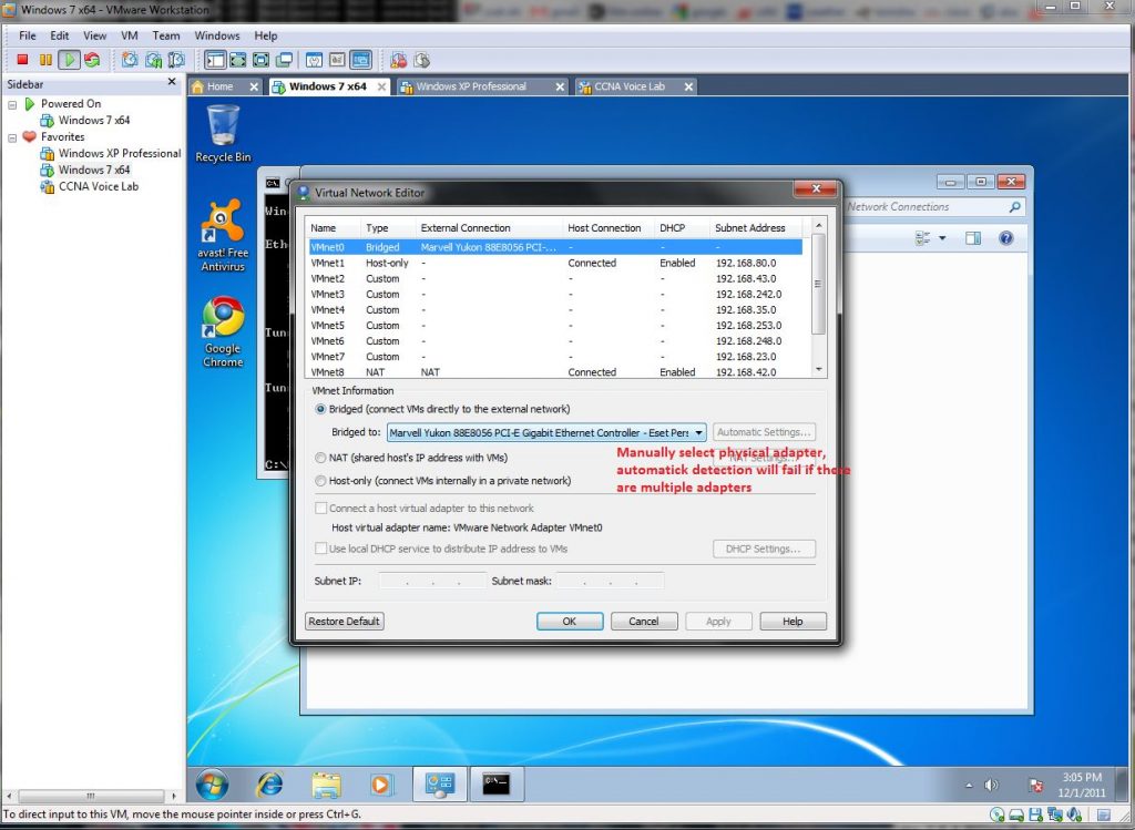
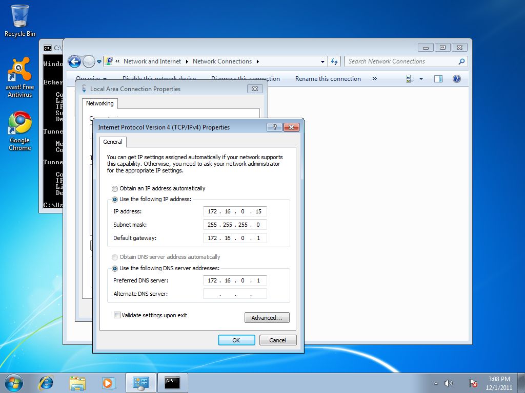
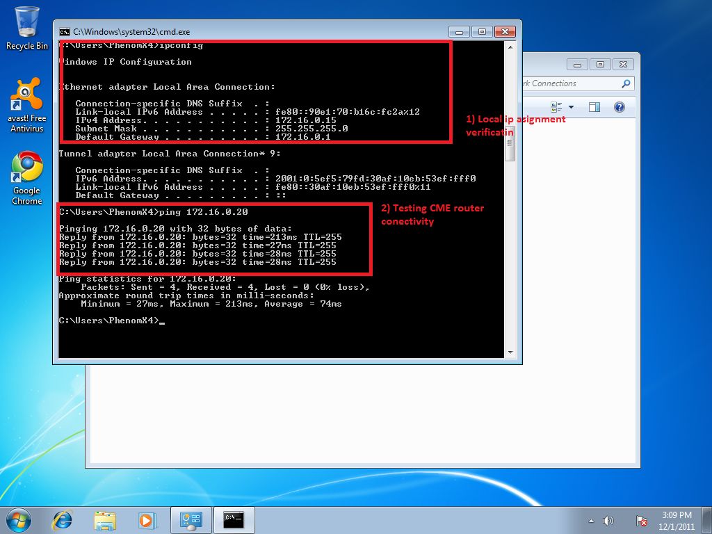
At first we must add second ephone (cheaper training solution is second cisco IP communicator) on VMware hosted client. As obvious install os on virtual PC. Next you need to configure network bridging with hosting pc. In our scenario hosting (physical PC) belong to network 172.16.0.0/24 with default gateway 172.16.0.1/24 and CME gateway was configured with 172.16.0.20/24, first ephone is on hosting pc with IP 172.16.0.10/24.
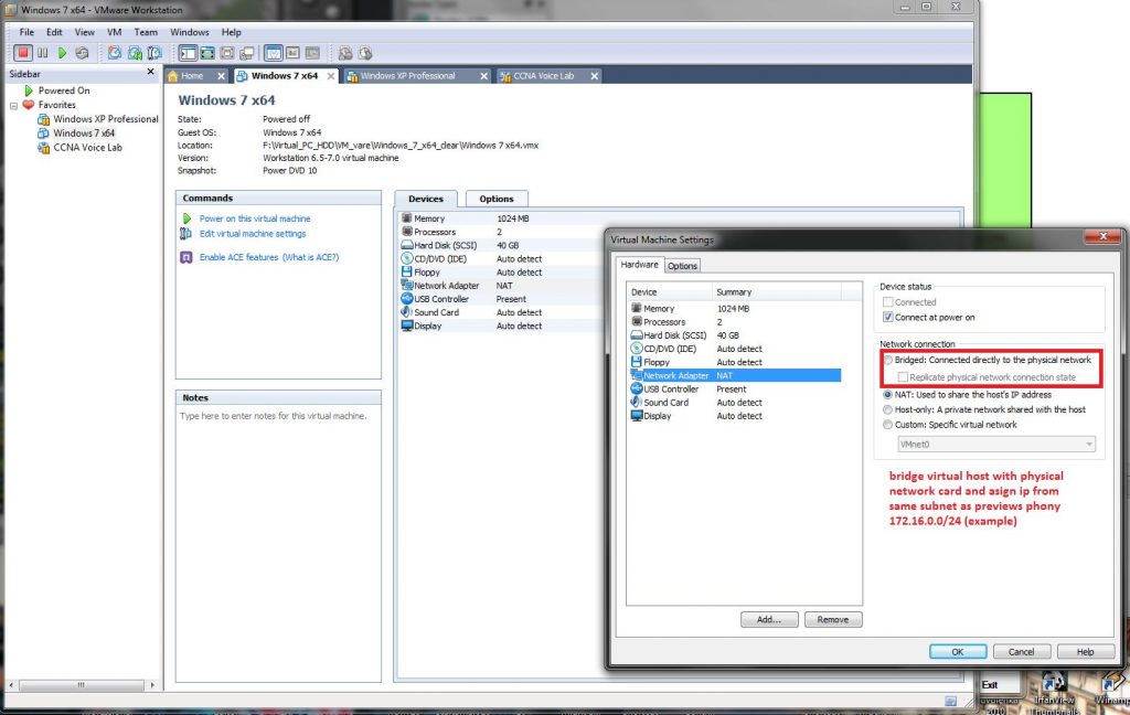
Setup process for bridging hosted pc to hosting network adapter is described in next pictures:
1) Open Virtual Network settings dialog and set bridged (not NAT)
2) If you have more than one installed network adapter (WiFi, second network card, or virtual card of VMware) you must manually select appropriate bridging adapter as hosting client physical adapter (better is if you check it)
3) Configure IP address in hosted PC (in our scenario we used 172.16.0.15/24 and 172.16.0.1 as default gateway) -address assignment must be derived from your home network config – CME router and ephones are in this simple scenario in same subnet.
4) Verification of local stack and connectivity with CME router 172.16.0.20/24 from hosted PC (installed in VMware)
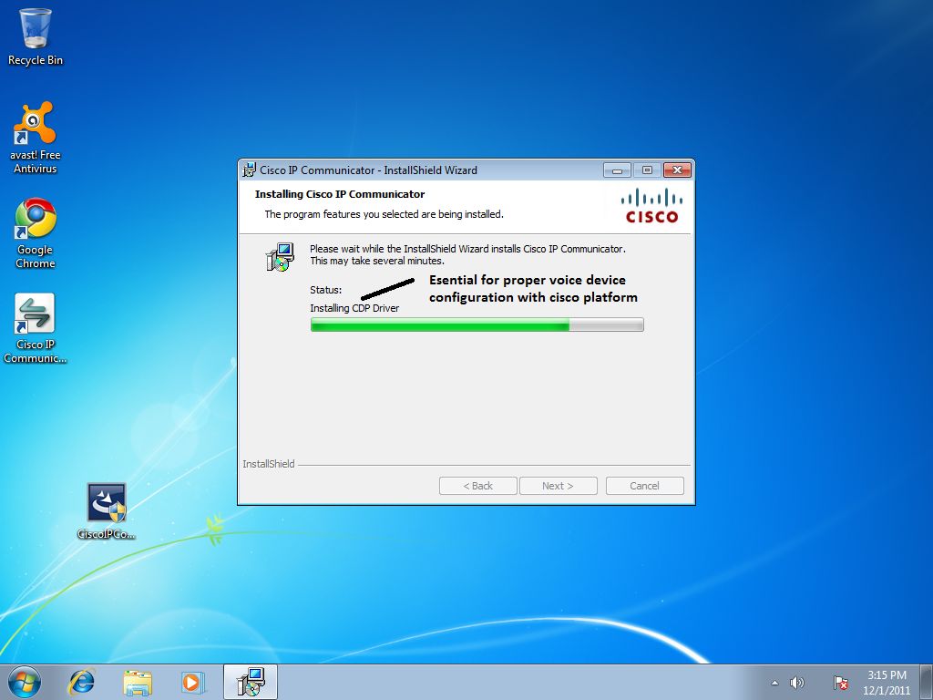
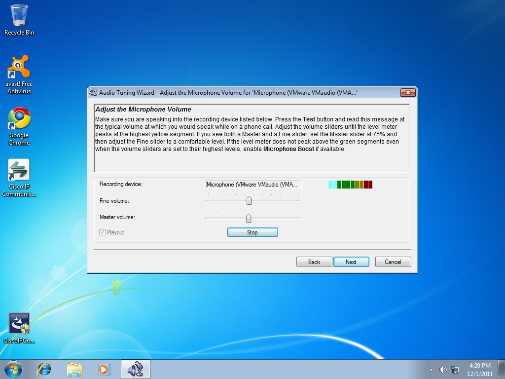
When we successfully configured network adapter bridging for hosted PC, next step is install and setup of cisco IP communicator:
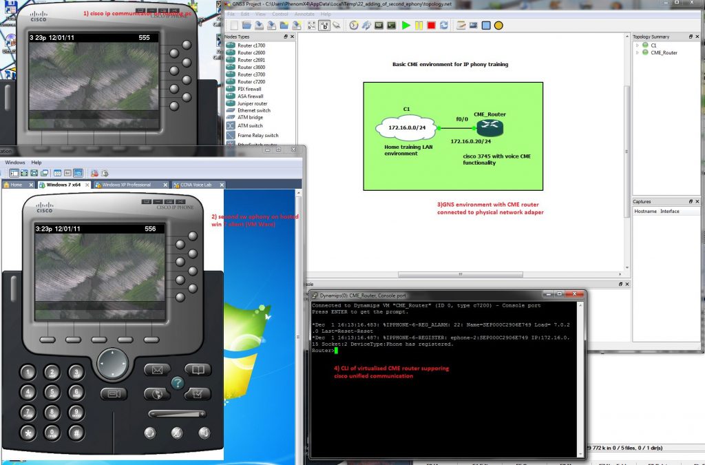
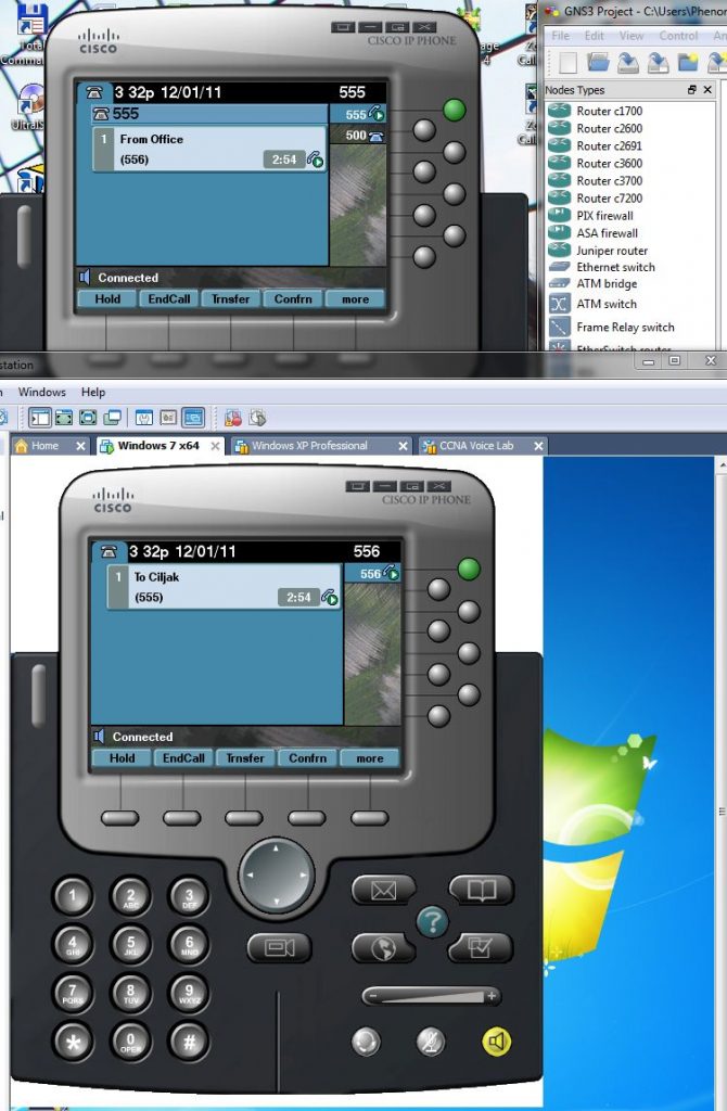
When all is done, our testing home lab will look like this:
Ephone at top is installed in hosting PC with 172.16.0.10/24 IP, bottom ephone installed in hosted (virtualized) PC with 172.16.0.15/24 IP and GNS emulated cisco IOS with telephony service has its fa0/0 interface configured with ip 172.16.0.20/24 and acting as CME router (voice gateway).
Our first tested config (it will be explained in next articles) is
ephone-dn 1
number 555
name Ciljak
!
!
ephone-dn 2
number 556
name Office
!
ephone-dn 3
number 500
!
ephone 1
mac-address 001E.8C02.BD12
type CIPC
button 1:1,2f3
!
!
!
ephone 2
mac-address 000C.2906.E749
button 1:2
— some output was omitted
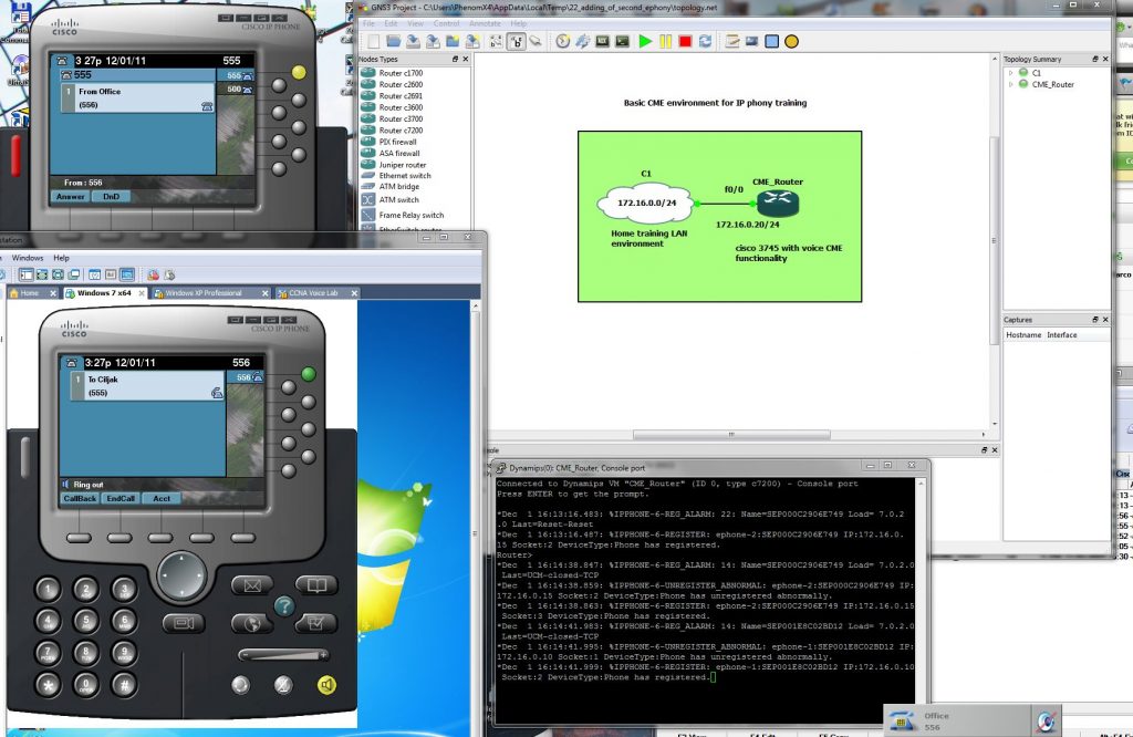
Now lets go for call placement from Office (bottom) ephone to Ciljak (me) top ephone:
Closer look at phones during call processing is:
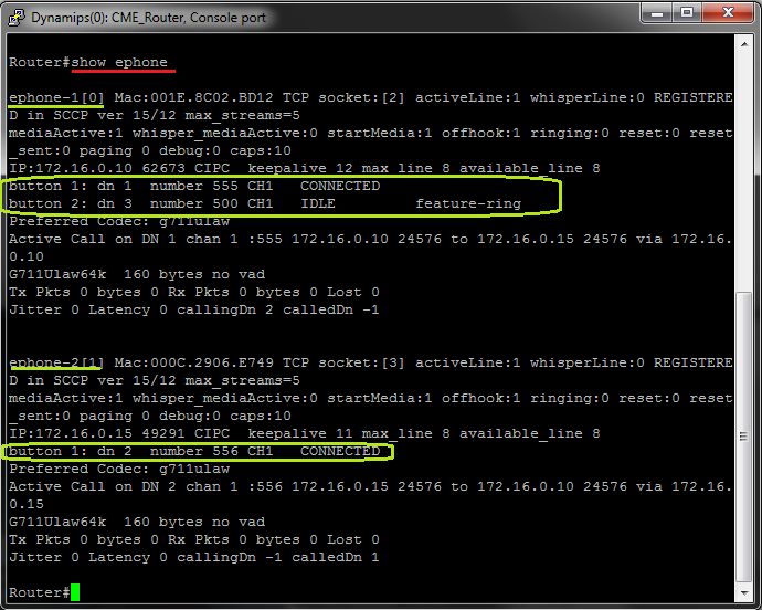
For obtaining info about ephones and ephone-dn to buttons (lines) of physical ephone use #show ephone CLI command:
12. Examination of VTP modes
VTP as Vlan trunking protocol make management of VLAN database across network simply but is proprietary. VTP allows configure appropriate VLANs on one switch (VTP server) and then propagate these VLANs to whole network (Other VTP server with lover revision number or other VTP clients).
But be careful when adding preconfigured switch – higher revision number take precedents and will populate preconfigured VLANs to entire network. Possibly best thing that you can du is change VTP domain name to another and then to expected because change in VTP domain name reset revision number to zero. Higher revision number mean „I have more accurate information about what is in network expected to do“.
Benefits of use VTP are:
consistency in VLAN across network
dynamic trunk configuration when VLANs are introduced to network
In VTP terminology we must concern with these terms
VTP domain – one or more interconnecting switch same VLAN configured. L3 devices dictate domain boundary.
VTP advertisements – distribute and synchronize VLANs
VTP modes – defines interaction with spread advertisements of VTP protocol across network
VTP pruning – restrict flooding traffic to switches where are not appropriate VLANs. Help save available bandwidth on network trunks.
VTP modes are:
VTP Server (default mode) – advertise VTP domain VLAN information to other enabled SW in same VTP domain (store VLAN info in NVRAM!!!). From server can be VLAN created, renamed or deleted.
VTP client – only stores VLAN info. Is not default – vtp mode client CLI command must be configured. can not any way change configured VLANs as server mode can, but accept server made changes (exception is higher revision number that can harm whole network – please before adding used switch to existing network reset revision number!!!!).
VTP transparent – forward VTP advertisement but do not participate on VTP.
Now we can take closer look at our training lab. Preconfigured scenario can be obtained from here (PKT 5.2 or above).
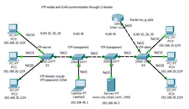
All switches participate on same VTP domain with name: myLab (please remember that names are case sensitive!!!). Switch S1 act as VTP server and can introduce and change VLAN to network. S4 is client switch that will accept VLANs modified by VTP server S1. Storage and administrative devices are connected to two switches S2 and S3. These are VTP transparent and contain only private VLAN 40 but trunk link between S1-S2-S3-S4-Inter VLAN router must be allowed for all VLAN (is default but show interface trunk and per trunk configured switchport trunk allowed vlan nr.nr, .. can help correct errors wen occur.).
Inter VLAN communication (reachability is enabled by router on a stick Inter VLAN router. If some access are expected be prohibited (access from clients to administrative VLAN with other ports as 80 and 443or 53 then appropriate access list must be created and assigned on appropriate interface to take effect.)
Now we can examine our topology:
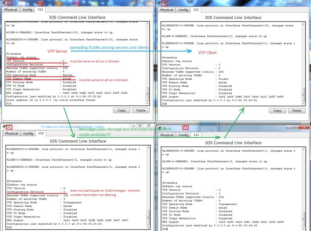
Status of VTP enabled protocol on S1 is displayed after typing command show vtp status under privileged exec mode or after do under other config modes
VLANs spread from S1 to S4 does not alter config on S3 and S2 in transparent mode.
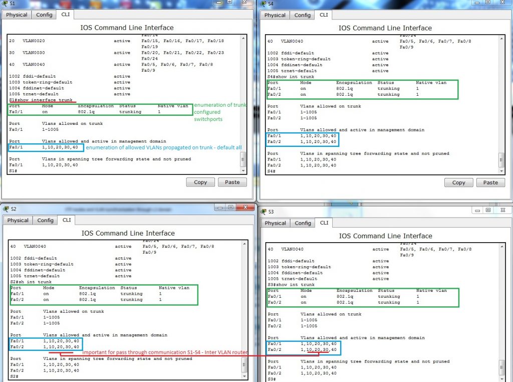
Examination of allowed VLANs on trunk link among switches – show interface trunk
Because default are allowed all VLANs to propagate across trunk, no additional commands are necessary – but keep in mind that they must be allowed or somebody for security reasons can enable only appropriate VLANs.
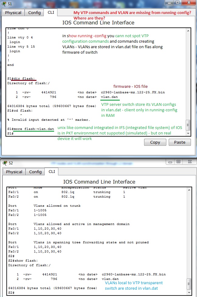
4. A bit confusing output from show running-config. You would by surprised where are all VTP config commands and VLANs that you created. But no worry, they are stored in vlan.dat in router flash. Vtp config can be examined with earlier mentioned commands. But next figure will explain something that you can be interested in.
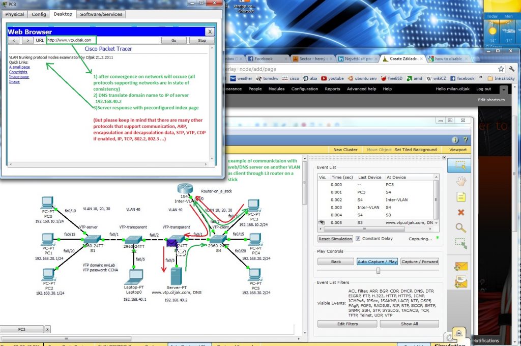
5. Example of real message exchange in training environment – web access. When there are devices on different VLANs they must communicate through L3 device (L3 traditional routing scenario, Router on a stick or introducing SVI interfaces on L3 capable switch). Now it is important feel all protocols that support exchange of messages through our network – HTTP, DNS, TCP, IP, 802.2 LLC, 802.3 Ethernet, ARP, routing protocols if needed, VTP, STP, CDP (on cisco network but all managed network use something), SNMP for management … and many many others. That all lies beneath network exchange of our communication (ICQ, e-mail, facebook, youtube, skype, VoIP …).
11. Examination of traditonal inter VLAN routing with dedicated routers
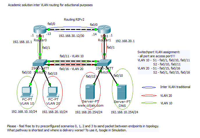
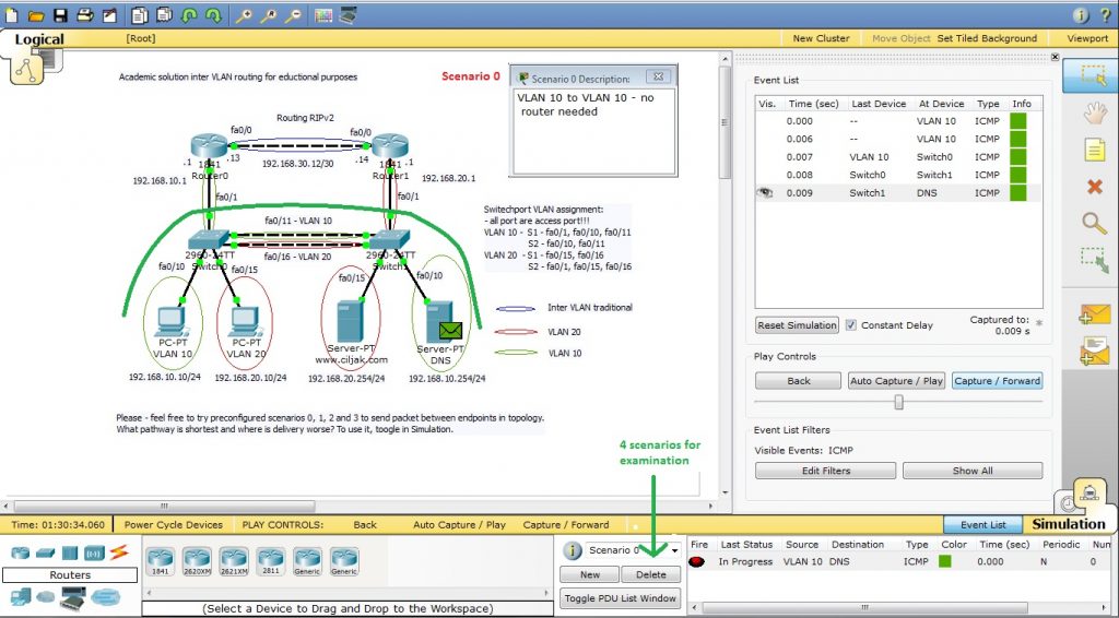
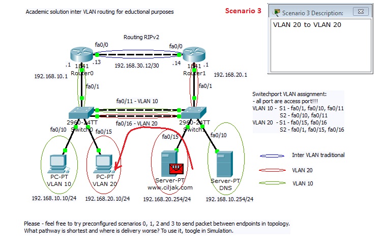
Our training lab will focus on „academic“ traditional inter VLAN communication. This routed connection uses two separate dedicated routers that are connected through two point fast ethernet speed connection (link). Our goal will be to understand how will data packet travel from one VLAN (red) to second VLAN (Green) using blue routed segment.
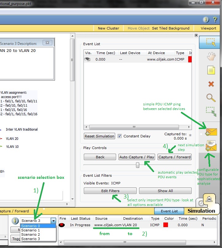
This scenario is bundled with 4 Scenarios that can be selected from scenario drop box in bottom part of Cisco Packet tracer (picture). For best PDU tracking go to simulation mode where you can look for events created during PDU traversing from source to its destination.
Scenario selection box is marked as nr. 1. Right pane consist of fire button that can optionally start PDU delivery from source to destination. Type mean PDU protocol and selectable color is color of PDU. Optionally can be altered PDU filter (default in this scenario will intercept only ICMP – ping PDU – ARP, RIP, STP, CDP … PDUs are hidden).
Now is all prepared for PDU delivery examination – open our scenario in PKT 5.2 or above and select scenario:
1) Scenario 0 – intra VLAN – from host 192.168.10.10 to DNS server 192.168.10.254 on same VLAN
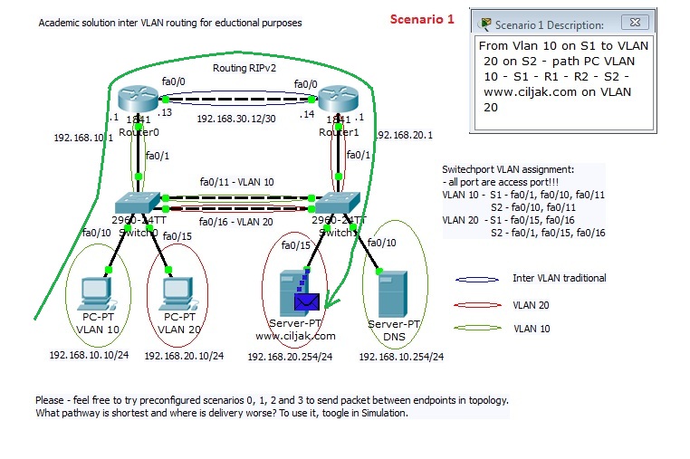
2) Scenario 1 – inter VLAN – from host 192.168.10.10 to www.ciljak.com server with 192.168.20.254 on different VLAN
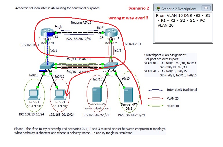
3) Scenario 2 – inter VLAN – from DNS server 192.168.10.254 to host 192.168.20.10 on different VLAN
4) Scenario 3 – intra VLAN – from server www.ciljak.com 192.168.20.254 to host 192.168.20.10 on same VLAN
Conclusion: Different path for inter VLAN routed PDU is one of many great weakness. Price of dedicated server and time for cabling that can lead to network failures is another great weakness. Better solution is introduction of L3 capable switch or cheaper but not so strong (sharing trunk that mean potentially bottleneck in network) is well know router on a stick solution.
You are strongly encouraged exchange access link between two switches with one trunk link with ether channel.
10. Rootbridge election process in STP enabled environment
In redundant L2 topology STP ensures loop free path for frames traveling among endpoints blocking redundant paths that cause a loop.
STP – spanning tree protocol uses STA (spanning tree algorithm). STA designates a single switch as root bridge and uses it as reference for all calculations. Switch with lowest bridge ID (BID) becomes root bridge. After root bridge is determined – STA calculates shortest path to root bridge. Each switch use STA determine which ports block. Until STA on all switches is calculated – all traffic on broadcast domain is blocked. Port costs and path to rood bridge are considered when determining which path to leave unblocked.
This article will focus on root bridge election in STP enabled network.
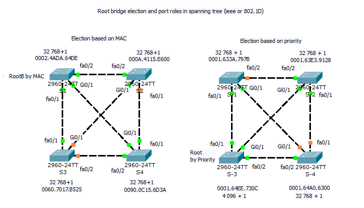
When root bride are elected this mechanism will be used:
1) lover priority – configured by spaning-tree vlan nr,nr, … priority nr (1 to 65 536 with increment 4096, default 32 768) is better
2) if priorities are equal (default 32 768) then lower MAC address is preferred by STA.
Our lab will use these 2 mechanism for root bridge election:
For configuration root bridge priority in 802.1D(W) on STP capable switches can be used CLI command:
sw(config)#spanning-tree vlan number priority Priority_number
example spanning-tree vlan 1,99,150 priority 4096
or
sw(config)# spanning-tree vlan nr root primary
sw(config)# spanning-tree vlan nr root secondary
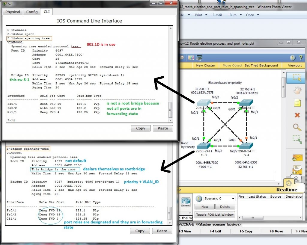
One of the most important thing is determine which switch is elected as root bridge using CLI commands. You can use show spanning-tree entered at privileged exec prompt as show next picture
What important thing show to us output from commands executed on two different switches?
1) Root bridge mark themselves as root bridge (this bridge is …)
2) All root bridge ports are in designated role and are in forwarding state
3) 802.1D implementation of STP is in use (not rapid-PVST) because ieee is in output
4) Priority 4096 was important for root bridge selection (if equal then lover MAC break the tie and S-1 going to be root bridge
Log in to Academy Connection (you must be a registered Networking Academy student, alumni, instructor, or administrator)
After logging into Academy Connection, select the Packet Tracer graphic to download.
Or you can use another method for obtaining it, at your mind must be that it will be version 5.2 or above.
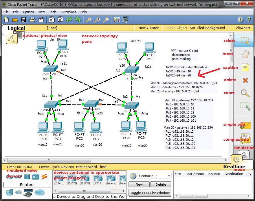
Closer look at GUI of our simulation application:
Next published articles focus on SOHO environment simulations or case study of some network configurations (single area ospf, wrong default route, AD route preference, STP, rapid STP …).
But there were presented only final topology with device configurations, closer description is for you. Please take my lab series only as a announcement of problems for solving and as a optional learning opportunity not as a substitution of labs spreaded with academy. All content is providet as is without any warranty to obtain you CCNA or CCNA Voice certification. There are many skills that must be gained.