1

MMU models slicing with PrusaSlicer and Prusa MMU2S

This article go step by step in proces of slicing Multi Material 3D model with PrusaSlicer with focus on appropriate extruder assignment, objects placement and check for correct layer placement.

First tips for MMU prints

After some time of using multimaterial upgrade MMU2S for Prusa i3 MK3S printer i can offer this example workflow for seamless MMU prints.

Best MMU material for MMU print for me is PETG. Filament is tought and mechanical resistant, gears does not demage it during permanent loading and unloading proces. Number of outer intervence is minimal. Something worse ist ABS but because it thermal sensitivity is appropriate for almost 2D prints (bookmarks, logos, …). Worst material is PLA, is beter dont use it because it low melting point and bad mechanical resistance (gears can easy demage it).

At the begining we can prepare our own model (this for interesting bookmarks or another logos can describe in another article) or download one from web.

Very important is, that full model must be divided in separate parts of appropriate colors that lays on on top of another or on one basement object. Very important is that they dont interfere one by another. And they must lay in way that one objects layer is on the top of another layer. There can not be any one free layer, because all final print will be demaged.

Selection of exercise modell

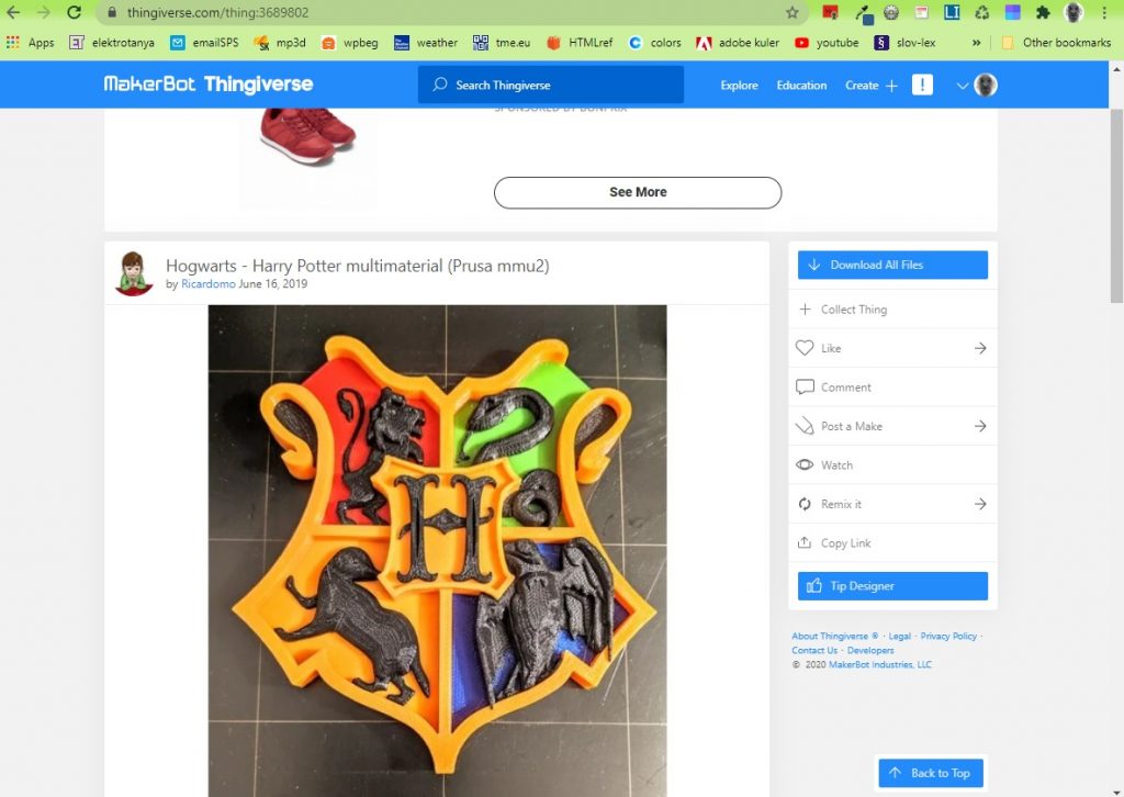
For our exercise we download model https://www.thingiverse.com/thing:3689802 from thingiverse. If you are interested for other models, please visit selection https://www.thingiverse.com/ciljak/collections/mmu .

After download unpack .zip file and run PrusaSlicer (this description use version 2.2).

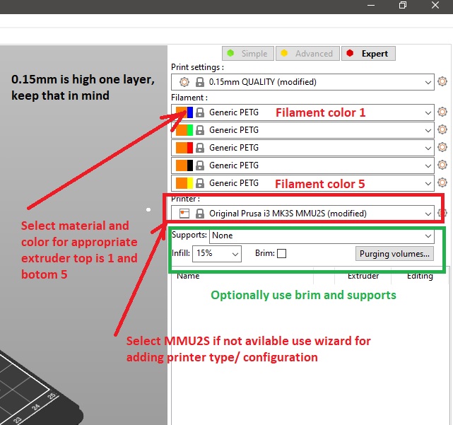
For basic setup must be done:

  • Selected quality – for good results select 0.15mm QUALITY
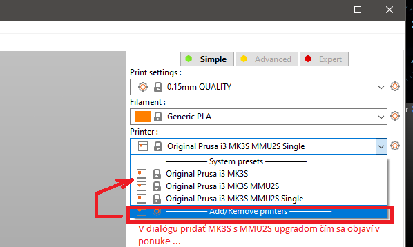
  • In section Printer select Original Prusa i3 MK3S MMU2S – if not awayable, please go through printer add wizard and instal printer with MMU upgrade (now we have option for MMU single or MMU as we selected on our next picture)
  • For all filaments select appropriate type and color of filament for visualisation (keep in mind that on the top is filament 1 and bottom filament 5, in this order with correct color they must be loaded into MMU2S upgrade on the printer)
  • Optionaly select supports or brim for better setling of the model

Before next step, we must look at our model and recognize what part is base on top of their are other parts added. In our exmple it is orange part. This part can be drag and drop into space of slicer. Other parts are added on the top and tne create final MMU composit.

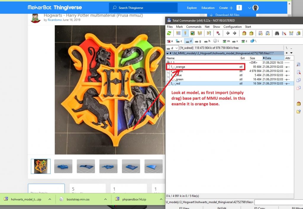
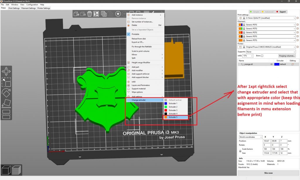
After import of first (base) orange part, we must rightclick on the object and select extruder with appropriate filament, in our case it is extruder 5 with orange filament.

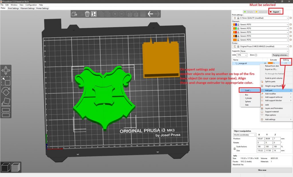
In next step we must switch on expert settings and on object pane (right bottom layered part) we click on add option (with sign + in circle). Next select add part and load one of remaining parts from disk. Our downloaded files are named by color in spanish, but it can be recognized or translated and refered with picture of modell on thingiverse.

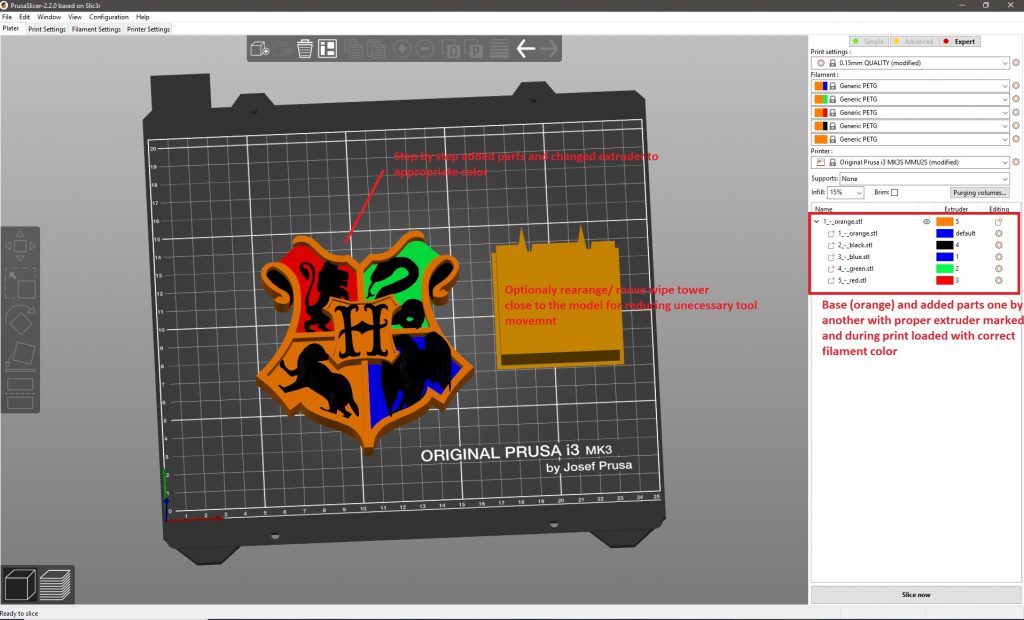
After adding first part, use rightclick on selected part and change extruder to appropriate color. Repeat his steps – add, change extruder to appropriate color until last part of model.

Optionaly you can change position of wipe tower. You can also rotate and change width of tower for better workflow of objects on headbed.

Tips and tricks


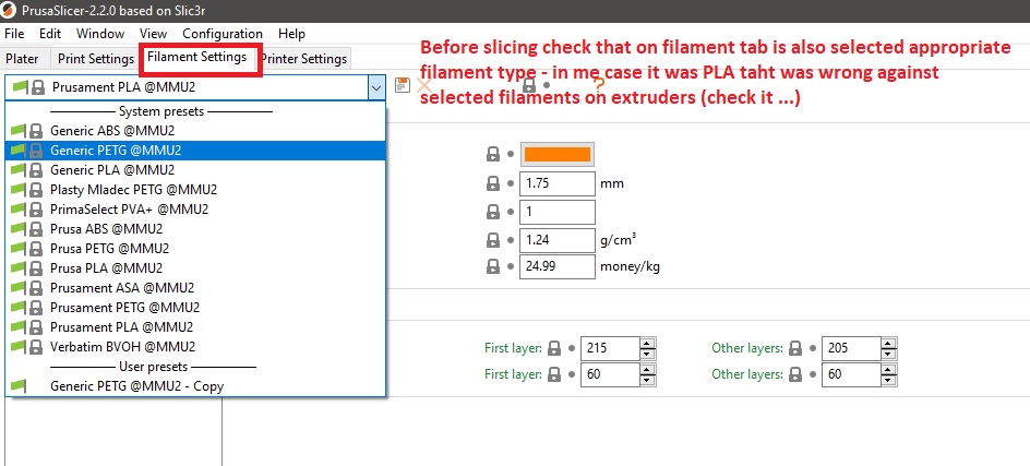
Important notice: Before final slicing, look at tab Filament settings and check if corect type of filament is selected. After initial opening od PrusaSlicer default settings was for PLA. We changet filaments for appropriate extruders but this selection does not automaticaly changed type of filaments. You must do it manualy, it was one of me big mistakes with new MMU upgrade.


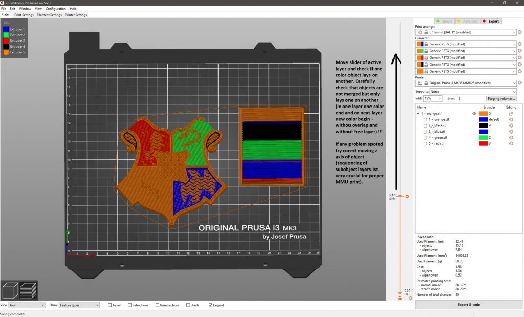
Important things to check after slicing: Slide with layer selector an check all color layer changes. On one layer can not be two or more materials with different colors in same place. Also one layer by another there can not be a free layer.

If you work on simple objects as bookmark or another promotional item it can by calculated that 4 layer with width of 0.15mm are together high 0.6mm. next added objedct (logo or text) must have their z axis on 0.6mm. And if this text or logo will have 3 layers it must have 0.45mm high because 0.45/0.15 is number 3.


Next picture show fully prepared MMU objects.

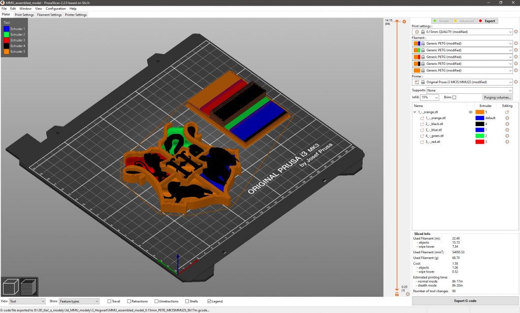
Prepared PrusaSlicer file can be downoladed for further study from here.


Tip for you: MMU can produce large waste of material when is used for large 3D ojects but it can be economical if you use it for some marketing things as bookmarks and logos of a company. Think about it before preparing model. Wery good scenario is singlecolor base and next logos and text with only few layer.


Showcase of multimaterial 3D prints


MMU2S kit assembling

This article contains photogallery from building the prusa MMU2S multimaterial upgrade kit.

Whole building process can be refered from official site here and consist from these main parts:

  • existing printer extruder upgrade
  • filament selector part assembly
  • final binding and electronics interconnection between printer prusa i3 MK3S and multimaterial upgrade prusa MMU2S


Multimaterial upgrade MMU2S for 3D printer prusa i3 MK3S

Creating a color model can be accomplished using several methods. In amateur work, the simplest but also the most workable solution is to print the original from white material and then paint it with a brush or airbrush.

In the case of fully automated machine 3D printing, two possible solutions are possible. The first, more expensive solution is to use several separate extruders. In this case, we eliminate the jamming of the filament in the feed path of the extruder, the perfection of the registration is problematic as well as in conventional offset printing.

The second cheaper solution uses a single extruder and a system for feeding print filaments from multiple sources. The second category also includes the so-called multimaterial upgrade for 3D printer Prusa i3 MK3S with designation MMU2.

MMU2S – the second generation of multimaterial printing extensions from Prusa research to the Prusa i3 MK3S printer. The homepage with the option to order via the e-shop is here.

It is clear from the previous video that we can use a total of 5 different materials for printing. As an interesting additional feature, the upgrade allows:

  • effective printing of water-soluble support materials (they will be used due to their price only on a thin layer, which will ensure a smooth separation of the support),
  • pressing of material residues on individual printing spools.

The procedure of assembling the supplied kit can be seen e.g. on video:

We have to prepare the model for printing so that each color will represent a separate .stl model. Before the first import, we must call up the option in PrusaSlicer (download here) via the Printer menu of the option to add a printer according to the following image:

First we add and place the first model, then all the others.
A brief procedure can be seen in the video from the upgrade creator in the following video:


Gallery of 3D prints

Schowcase of my scuccessfull 3d prints contain next photogallery. As inspiration for my prints was used:


3D printing with Prusa i3 MK3S

3D printing is additive technology for device prototyping. If you are interested in budget but very durable and affordable device i can recommand you printers by Joseph Prusa (homepage https://www.prusa3d.com/ ).

World known model is Prusa i3 MK3S taht can be obtainted as fully assemled model https://shop.prusa3d.com/en/3d-printers/181-original-prusa-i3-mk3s-3d-printer.html for 999€ or as kit with lower cost 769€ https://shop.prusa3d.com/en/3d-printers/180-original-prusa-i3-mk3s-kit.html .

If you have a time the best way for obtaining a prusa 3D printer is by assembling it. Next galleery show how i build my printer.


Assembling kit include great assembling manual, but you can in all time refer online manual here https://help.prusa3d.com/en/category/original-prusa-i3-mk3-kit-assembly_336. Another way how to preare for buld is through youtube bulding marathons. As examle of these bulding marathons you can watch:

or as very quick preview

After successfull assembling you must gou through selftest of device. All axis callibration process and very crucial part of all good print is Z-axis calibration and when is necessary live Z- adjustment. All my mistakes are related to:

  • bad Z- axis calibration – to low or to high position of extruder nozzle
  • loosen gear feeding filament in extruder (inconsistent print)
  • innapropriate material for printedobjects (bad results if you use ABS for higher model and room temperature is not constant)

Quick introduction of most common problems and ho to suppress it are contained in next video


Program-controlled backlight of the Witcher figure series

The project of program-controlled backlighting of collector’s figurines combines the practical use of arduino IOT modules to provide program-controlled lighting effects as well as the application of LED lighting.

Requirements for the final proposal:
  • the ability to independently control the light intensity and color tone of the light in a group of 6 collector’s figures,
  • the selection of the backlight program mode must be possible by means of the IR remote control,
  • the control module must be compactly integrated in the protective cover,
  • the power supply is solved by means of a small pulse source,
  • the output power must be sufficient for backlighting consisting of 2 * 3 RGB leds with a consumption of about 10mA per segment (expandable to 9 or 12 collector figures.

The control electronics module consists of a pulse power supply with an output of approximately 30VA. The Arduino Mega module was used as a control module due to the sufficient number of programmable PWM outputs. The PWM output makes it possible to ensure the gradual switching on and off of the individual light strips placed in the packaging of the collector’s figures.

Problems in the implementation phase and their solutions

In the conceptual design phase, despite the selected module, I encountered the problem of insufficient number of PWM outputs, which I solved by introducing a two-state control for the red backlight component (this is a compromise solution).

Power amplification of the outputs is achieved by using Darlington transistors TIP120 purchased from e-bay.

Description of the technical solution of the backlight

The backlight of each figure consists of a pair of LED strips, a part with warm white and an RGB strip. The pictures in the photo gallery show a more detailed link.


Block diagrams of electronics modules

The connection of the control module with the block of Darlington transistors is shown in the following figures (block interconnection diagrams).

The procedure for 3D printing of the protective cover is shown in the following photo gallery.


Tom and bottom part aligned for testing purpousis
Fully printed bottom part of cover
Control electronics mounted into a 3D printed cover
Side look at cover
Bottom part of cover sliced
Top part of shiled sliced
3D model for electronics cover
Tom and bottom part aligned for testing purpousis

Demonstration of the control program

You can download one of the driver versions as an arduino sketch.

I firmly believe that this text will serve as inspiration for the backlighting of other collector’s collections.