1

17. Port security on access layer switchport

Port security is feature that enable permit or deny traffic for end user PCs connected to access layer switch. Port security enable specify a group of valid MAC address on port. If maximum secure MAC address  is reached then security violation modes lead to protect, restrict or shutdown of port.

There are 3 ways how to configure port security:

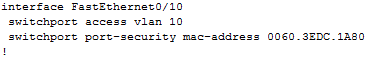
1) Static secure MAC addresses – manually configured with

   switchport port-security mac-address MAC_ADDRESS

2) Dynamic secure MAC address – dynamic learned and stored only in address table (after restart cleared)

3) Sticky secure MAC address  – mac address are learned dynamically and saved in running config (next can be merged with startup config).

Default port security:

– disabled on port -> switchport port-security

maximum nr. of secure MAC: 1

violation mode: shutdown

sticky address learning: disabled

Sample configs:

A) Dynamic port security configuration

s1#configure terminal

s1(C)# interface FastEthernet0 0/10

s1(c-if)#switchport mode access

s1(c-if)#switchport port-security

s1(c-if)#end

B) Sticky port security – can configure max. nr. of secure mac address, in this example we configure shutdown as the violation mode

s1#configure terminal

s1(C)# interface FastEthernet0 0/10

s1(c-if)#switchport mode access

s1(c-if)#switchport port-security     (enable port security)

s1(c-if)#switchport port-security maximum 20 (maximum nr. of secure address)

s1(c-if)#switchport port-security mac-address sticky    (enable sticky learning)

s1(c-if)#end


Table: Security violation modes

Violation

mode

Forward

traffic

Send syslog

message

Display error

message

Increase violation

counter

Shuts down

port

protect no no no no no
restrict no yes no yes no
shutdown no yes no yes yes


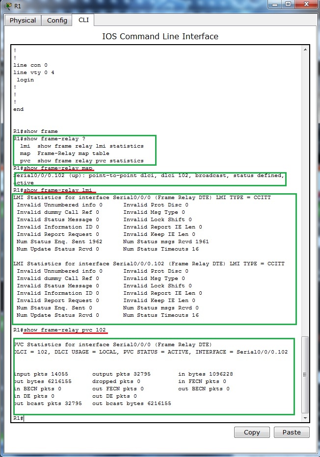
Verification commands:

  • show port-security  [interface interface-id]
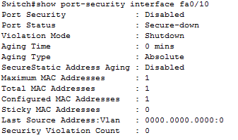
  • show port-security  [interface interface-id] address

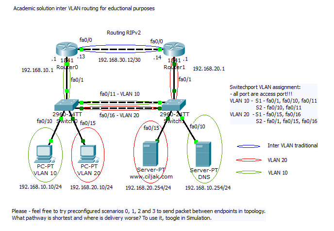
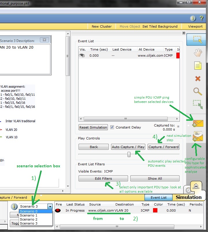
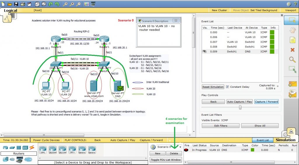
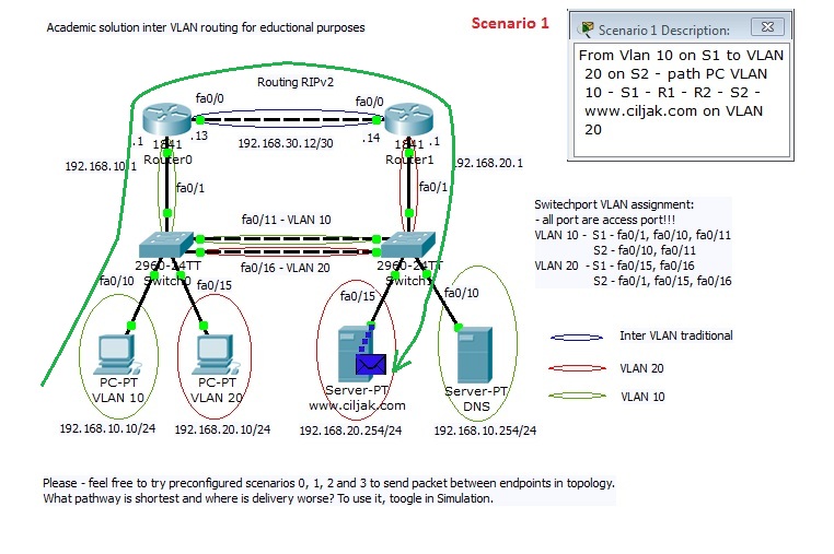
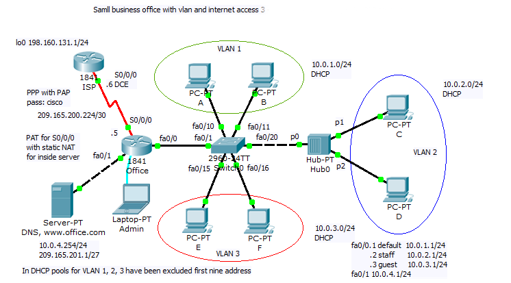
Our training scenario focused on port-security can be obtained from here (Packet tracer 5.2 or above you will need).

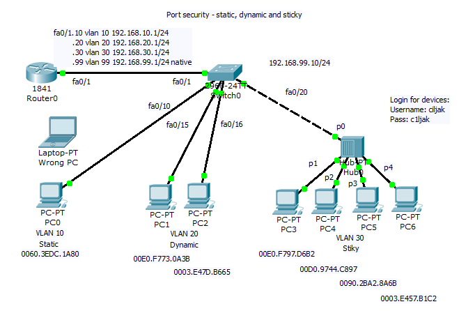
Network topology  consist of router acting on stick and switch. Port security is configured sticky for 10 mac address for port 20 to 24 with commands:

interface FastEthernet0/20
 switchport access vlan 30
 switchport port-security maximum 10
 switchport port-security mac-address sticky 
!
interface FastEthernet0/21
 switchport access vlan 30
 switchport port-security maximum 10
 switchport port-security mac-address sticky 
!
interface FastEthernet0/22
 switchport access vlan 30
 switchport port-security maximum 10
 switchport port-security mac-address sticky 
!
interface FastEthernet0/23
 switchport access vlan 30
 switchport port-security maximum 10
 switchport port-security mac-address sticky 
!
interface FastEthernet0/24
 switchport access vlan 30
 switchport port-security maximum 10
 switchport port-security mac-address sticky 
 
 
You are strongly encouraged to try 
 
1) Static port security for PC on vlan 10 on port fa0/10 with mac 0060.3EDC.1A80 – then disconnect device with mentioned mac and attach device with wrong mac (examine shuting down state of port), then correct port state and enable traffic forwarding.

2) Enable dynamic learning for PC on ports fa0/15 and fa0/16.

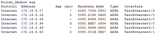
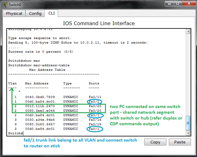
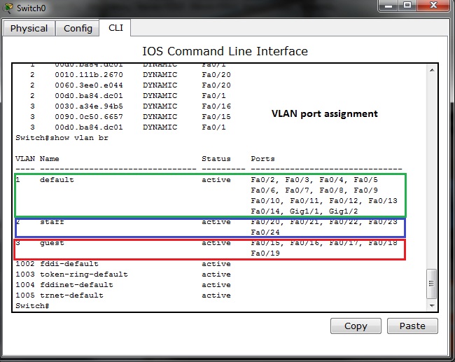
As example, output from show mac-address-table of switch

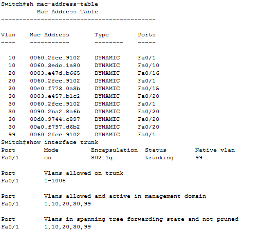
On port fa0/20 can be spot shared network segment (in our case it is hub interconnected segment).


16. Administrative Distance and route source preference

In environment with 2 or more enabled routing protocols must be present mechanism for selection of routing sources that are learned. What routing protocol obtained routes for remote network will be introduced to routers routing table? That is a big question.

Administrative Distance in short AD is considered parameter that will break the tie and say about trustworthiness of routing source.

Table of administrative distance of routing protocols
Routing source

AD  

(administrative distance)

connected 0
static 1
EIGRP summary route 5
External BGP 20
Internal EIGRP 90
IGRP 100
OSPF 110
IS-IS 115
RIP 120
External EIGRP 170
Internal BGP 200


Say in other words – AD is number from interval <0,  255>. And lower is better that mean static route (AD=1) is preferred over OSPF learned route (AD=110).

Training scenario focus on introduction routing sources (learned route) from RIP, EIGRP and OSPF routing protocols.

Fully configured lab. scenario for Cisco Packet Tracer 5.2 or above can be obtained from here. Topology diagram show next picture.

Routing protocols configuration is

Router_A Router_B
router eigrp 100
 passive-interface FastEthernet0/0
 passive-interface FastEthernet0/1
 passive-interface FastEthernet1/0
 network 172.16.5.0 0.0.0.63
 network 10.1.1.0 0.0.0.3
 auto-summary
!
router ospf 100
 log-adjacency-changes
 passive-interface FastEthernet0/0
 passive-interface FastEthernet0/1
 passive-interface FastEthernet1/0
 network 172.16.5.0 0.0.0.63 area 0
 network 10.1.1.0 0.0.0.3 area 0
!
router rip
 version 2
 passive-interface FastEthernet0/0
 passive-interface FastEthernet0/1
 passive-interface FastEthernet1/0
 network 10.0.0.0
 network 172.16.0.0
!
ip classless
router eigrp 100
 passive-interface FastEthernet0/0
 passive-interface FastEthernet0/1
 passive-interface FastEthernet1/0
 network 172.16.5.128 0.0.0.63
 network 10.1.1.0 0.0.0.3
 auto-summary
!
router ospf 100
 log-adjacency-changes
 passive-interface FastEthernet0/0
 passive-interface FastEthernet0/1
 passive-interface FastEthernet1/0
 network 172.16.5.128 0.0.0.63 area 0
 network 10.1.1.0 0.0.0.3 area 0
!
router rip
 version 2
 passive-interface FastEthernet0/0
 passive-interface FastEthernet0/1
 passive-interface FastEthernet1/0
 network 10.0.0.0
 network 172.16.0.0
!
ip classless

EIGRP and OSPF routing protocols will create neighborship relation between facing interfaces. This mechanism is important for generate triggers after breaking relationship after topology change in network and cause generating and spreading routing protocols PDU, algorithm recalculation and rearrangement in routing table.

If routing table is missing expected route please take a look at creation of neighbor relation and verify appropriate timers that trigger sending hallo packet or define time for detaching route from table after their potential error.

Important commands for troubleshooting at CCNA level are:

  • show ip eigrp neighbors
  • show ip ospf neighbor
  • show ip ospf interface INTERFACE
  • show ip route
  • show ip protocols

Output from neighborship verification commands are

Now we can look at routing table both router A and B. What we can to expect? Which routing protocol introduce their route to routing table? Lower AD is preferred and lowest AD has EIGRP!

But what is wrong, routing table show only classfull D (Duall EIGRP route) that point nowhere (Null0)? Can you mentally answer why it is so? What is wrong in our config? Classless VLSM route (network mask is longer as appropriate classfull mask) are introduced by OSPF because OSPF is inherently classless routing protocol.

Please remember that null0 classfull route introduced to routing table by EIGRP protocol (leading D for that route) is because auto-summary was not suppressed and is in use. For correcting this behavior on our network we must type no auto-summary on router-config command prompt of router eigrp 100.

All that was we describe is recorded from output of CLI Router_A and Router_B on next picture.

———————-

One of many processes that run on our router is mapping L3 address to L2 mac address on Ethernet interfaces. Info about learned relationship between L3 and L2 address offer ARP table of router. Their output can be visible after typing show arp on privileged exec of CLI (output depend on previews communication, arp cache is dynamic table that is aged after appropriate time non use of connection. That mean, if you will have all mac in table you must make ping sweep).

Records with character – in Age column is local interface of device. These records are excluded from aging mechanism! (- mean local interface on device, other are learned through ARP protocol)


15. PPP and Frame relay in small network

PPP and Frame relay are protocols operating at data link layer used in segment of private WAN connection. PPP enable establish communication through serial link between cisco and noncisco device where can not be used proprietary HDLC cisco encapsulation. Frame relay networks offer packet switched technology in providers network.  This article will focus on simple implementation of PPP serial link and Frame relay link in office environment.


About PPP (basics)

Is nonproprietary data link protocol carefully designed for compatibility with common HW devices. Enabled are these connection establishments:

  • serial cables
  • phone lines
  • trunk lines
  • cellular telephones
  • fiber optic links

Extend features supported on serial links as quality management and PAP or CHAP authentication mechanism.

Main components of protocol are:

  1. HDLC protocol for encapsulation over point to point link
  2. Link control protocol – establish link connection
  3. Network control protocols (NCPs) – for establishing and configuration different network layer protocol

PPP configuration step by step

1) Enable PPP on interface

R #config t

R(config)#interface serial 0/0/0

R(config-if)#encapsulation ppp

2) Configure authentication 

  • PAP – older and unsecure, password is send as clear text
    ppp authentication pap
    ppp pap sent-username My_name password PSWD
  • CHAP – based on 3 way handshake mechanism using message digest – preferred if can be used
    ppp authentication chap
     

3) Optionally configure compression with compress command

4) Optionally enable link quality monitoring

     ppp quality 80 (1 to 100) – if link does not meet quality requirements then goes down

5) Optionally enable load balancing across link with ppp multilink


About Frame relay

All frame relay networks are build on 3 main components: DTE equipment at each end of connection (FRAD device of user), DCE (telephony company CO) and middle components (frame relay switches in operator network).

In frame relay networks our routers act as DTE devices and serial connection T1/E1 leased lines connect router to FR switch in POP (point of presence) our ISP (internet service provider). Frame relay switches on other end act as DCE devices.

DLCIis local meaning number that identify link connection (but in opposite of IP address have only local meaning).

Frame relay address mapping is important for knowing how map which DLCI map to L3 address of remote destination. Mapping can be configured as dynamic or static. (for beginners is it a bit confusing in configuration and in CCNA eLearning materials). For configuration easier way is relay on dynamic mapping that use inverse arp. For static mapping must be used frame-relay map command.

Frame relay configuration step by step

1) Enable frame relay on interface

   encapsulation frame-relay

and set encapsulation options cisco /ietf, cisco is on cisco devices default. IETF use only in multivendor environment when second end is non cisco device.

2) Configure bandwidth (does not affect real bandwidth) that is important for EIGRP and OSPF metric calculation

3) Set appropriateLMI type (cisco, q933a or ansi)

4) Optionally disable inverse arp for frame-relay DLCI mapping and configure appropriate static frame-relay map commands (important in end-to-end reachability in hub and spoke networks when spoke to spoke reachability is expected).


For training and hardening skills before CCNA examination we introduce next configuration scenario that can be as preconfigured downloaded from here.

Scenario include PPP and frame relay configuration,  subnetting and dynamic routing using OSPF routing protocol with ID 999. Office network use private addressing space with subnets 192.168.10.0/24, 192.168.11.0/24, 192.168.30.10 and 10.0.0.0/8 (10.1.1.0/30 and 10.2.2.0/30 VLSM subnets). On router R1 is configured NAT with PAT for private client address space and static nat translation for remote access to internal servers.


For PPP link configuration on R2 and R1 router  we use

username R1 password 0 ciscochap username R2 password 0 ciscochap


interface Serial0/0/1
 ip address 10.1.1.2 255.255.255.252
 encapsulation ppp
 ppp authentication chap


interface Serial0/0/1
 bandwidth 2048
 ip address 10.1.1.1 255.255.255.252
 encapsulation ppp
 ppp authentication chap
 ip nat inside
 clock rate 2000000

For Frame relay configuration at R1 FRAD and R3 FRAD we used (configuration of FR switch is beyond scope of our training but Packet Tracer offer Cloud-PT simulation object that we will introduce in one of our next article).


R1 R3
 
interface Serial0/0/0.102 point-to-point
 ip address 10.2.2.1 255.255.255.252
 frame-relay interface-dlci 102
 ip nat inside
 clock rate 2000000
 
interface Serial0/0/0.201 point-to-point
 ip address 10.2.2.2 255.255.255.252
 frame-relay interface-dlci 201
 clock rate 2000000

For examination of frame-relay open state and mapping remote address to local DLCI can be used this show commands:

  • show frame-relay pvc
  • show frame-relay map
  • show frame-relay lmi
  • show interface

Output from this commands show next pictures

Output from show frame-relay lmi supply us with statistic information about link. LMI as management build in mechanism can be used for link state monitoring. As frame relay lmi standard can be selected cisco, q933a and ansi. As it is discussed in this topics http://www.tek-tips.com/viewthread.cfm?qid=402209, 21.3.2012 most important thing to consider is that both end must support apropriate type of LMI.

Output from show ip interface brief contain physical link and data link up state. If link state is down you need check clock rate command on DCE end of link, encapsulation command and authentication mechanism if used (optionally compression and other optional config).

Next pictures show output from show interface on interfaces participating in PPP encapsulation. As you can see from output of command encapsulation is PPP and both LCP and appropriate NCP (IPCM and CDPCP) are in open state.

For further reference about connected serial cable and clocking of link you can use show controllers serial – interface s0/0/1 on R1 router act as DCE end with configured clock rate command.

Last two pictures show Frame-relay simulation device available in Cisco Packet tracer.


14. Wrong default route propagation in OSPF enabled network

Default route introduce ultimate outgoing interface for L3 PDU from our network. Most common use is in stub-networks where is only one interface pointing to outside network (in this case is no need for load balancing between two or among ISPs interfaces). Instead of routers having to store routes for all of the networks in the internet, they can share a single default route to represent any network that is not in the routing table.

In small office networks is static routing and manual default route settings in use but in large network or in much more flexible network scenarios are dynamic routing protocol introduced.

Static default route can be propagated from router where command ip route 0.0.0.0 0.0.0.0 interface/IP_of_next_hop to all other routers in network.

How to enable default route distribution to network with most common IPv4 routing protocols?

1) Configure static default route on router that act as network boundary to ISP network with command:
      ip route 0.0.0.0 0.0.0.0 interface/IP_of_next_hop

2) Default static route needs to be advertised to all others routers that use dynamic routing protocols

  • for RIP1/2 use router command: default-information originate
  • for EIGRP use router command: redistribute static
  • for OSPF use router command: default-information originate

But what is happen when wrong default route is introduced in network topology? How troubleshoot problem with wrong default static route? We going to explore how this condition affect our production network and how to fix it.

Preconfigured scenario in cisco packet tracer 5.2 or above can be obtained from here. Small office network in this scenario look like this

Network topology consist of central router (act as boundary between office network and WAN) and one branch router (for simplicity is there only one branch router). All end devices are on separate networks and private address space is in use in internal network. Wrong default route 

ip route 0.0.0.0  0.0.0.0 serial0/0/1 (correct it is serial0/0/0) introduce in network routing loop that we will examine.

Our lab include option for sending ping and follow what is happen. Toggle to simulation mode and Auto capture/play.

Wrong default route lead PDU to its origin and Branch router loop back to central router with default route. L3 PDU contain mechanism how to break endless looping of PDU – TTL in data packet header is decreased after L3 routing to appropriate interface as you can see on next picture (PDU examination in cisco packet tracer – simulation mode).

Output from most common troubleshooting command show ip route that output from routers routing table issued on both routers is:

Now is time correct our mistake. What we need to do? At first you must remove wrong default route. There is no way how to change existing static route. First remove wrong route with command

no ip route 0.0.0.0 0.0.0.0 serial0/0/1

that point not to ISP router but back to internal Branch router and cause routing loop. Next step is introduce appropriate (correct) default route this way:

ip route 0.0.0.0 0.0.0.0 serial0/0/0 

and now we going to examine output from show ip route. But you will obtain problem that is cause of my mistake. In routing table is not default route introduced. Keep in mind that static route (but all routes) is in output only when appropriate outgoing interface is on. Then we will examine up state of s0/0/0 interface. As you can see physical layer is Up but protocol is down. 

S0/0/0 interface on Central router is connected to ISP with PPP link that use chap as authentication protocol. We need examine clock command on DCE end of serial link and then authentication credential on bot end of link.

And there is the problem, ISP side is supplied wit incorrect name of Central router. there is a typo Cnetral and correct it may state Central.

Default route is now correct but can we establish a connection between end devices on office network and ISP? Fire ICMP packet to destination nework 198.160.131.1. Packet can reach ISP router but then is discarded because no translation to public network have not been made. We are closer to our goal, data re well routed but address translation on private network boundary must be established.

For ISP (internet access – now without security configuration) connection in network with many clients I decided for NAT (network address translation) with PAT (port address translation) on interface s0/0/0.

At first we must create standard access list (i use named but also can be used numbered)

ip access-list standard NAT

permit 172.16.0.0 0.0.15.255

permit 172.16.16.0 0.0.15.255

permit 172.16.32.0 0.0.15.255

permit 172.16.100.0 0.0.0.3

and then enable nat translation with command

ip nat inside source list NAT interface s0/0/0 overload

most common beginners (also me) mistake is forget mark appropriate interface as ip nat inside and outside. in our case it is:

interface s0/0/0

ip nat outside

interface s0/0/1

ip nat inside.

Now we can place simple PDU between appropriate ends.

As „how to?“ training you can establish connection for inside servers and enable reach them from ISP side. There must be used static nat and address range for inside global must increase from 200.0.0.0/30 to minimal 200.0.0.0/29 as it state previews picture.

Final and fixed packet tracer lab is on next picture and for your training can be obtained from here (PKT 5.2 or above).


13. STP port roles selection

For port roles selection is important which switch is selected as root bridge. That mean after root bridge selection process (in fact during this process) are port roles determined. (we will discus 802.1d STP, difference in 802.1w rapid STP will be explicit marked in document).

In stable converged L2 topology with STP support are there these types of ports:

  1. Root ports – exist on non- root bridges and are switch ports with best cost path to root bridge.
  2. Designated ports – exist on root and non-root bridges. For root bridge all ports are designated ports!!! (quick examination but there can be confusion if root-bridge role is distributed among VLANs or when there is default VLAN root bridge selected with other mechanism as other VLANs). Please keep in mind that on segment is allowed only one designated port!!!. Designate ports also as root ports are capable populate mac-address-table (CAM table of switch).
  3. Non-designated ports – switchport that is blocked (in 802.1W rapid STP is used term alternate ports in discarding state).
  4. Disabled port – is administratively down (has no function or does not participate in STP).

STA (spanning tree algorithm) determines which port role is assigned to each switchport:

  • switch port with lowest overall path cost to root bridge is root port
  • in network topology all switches except root bridge have a single root port
  • if 2 ports have same port cost – switches uses customizable port priority value or lowest port ID if both port priority value are same (if cost is same – >  lowest port ID – >  if equal port ID break the tie, that mean Fa0/1 < Fa0/2 < Fa0/3 …. As example port fa0/0 default priority is 128.1 configurable_priority.portID). As configurable priority can be used number from 0 to 240 with increment 16, and lower priority is better/ preferred.


Example of port priority configuration:

S#configure terminal

S(configure)#interface fa0/1

S(decision-if)#spanning-tree port-priority 112    (0 – 240 increment 16)

How is port role lowest made?

  1. Switch with lowest bridge priority (if equal lowest MAC address) is selected as root bridge.
  2. Root bridge set all its port as designated (in stable topology are in forwarding state).
  3. Other, non-root bridge switches set one port with lowest cost to root-bridge as root ports.
  4. In shared segment are determined port roles way that set one port as designated per shared segment and all other set as non-designated (prevent L2 loops and broadcast storm arisen). Keep in mind that lowest priority is first, only if equal then port priority or portID is used for tie breaking!!!

When we repeat basic theory, now we can prepare our PKT simulation lab. Preconfigured scenario in Cisco Packet Tracer 5.2 or above can be obtained from here. 

Scenario consist of 4 switches. Root bridge role is determined by spanning-tree vlan 1, 10, 50 priority 4096 command for switch A. For VLAN information consistency is used proprietary VTP protocol with VTP domain: CCNA and password: stpprotocol. For redundancy of server roles in VTP two switches A and B are configured as VTP servers. Inter VLAN communication establish router on a stick  Inter-VLAN.

Staff PCs are on VLAN 10 and office web and DNS server is on VLAN 50 and use IP address 10.5.0.254/24.

Host Staff PCs obtain address automatically by DHCP that exclude first nine IP address from address pool.

As it was mentioned earlier root bridge can be noticed by two way from show spanning-tree command – explicit marking themselves as root bridge: „This bridge is root bridge“. Second way how to examine root bridge from output of show spanning-tree command is by fact that all port of root bride are set as designated. Next picture show output from switch A

Now we will take closer look on port role selection in training environment

Process that lead to convergence in L2 topology is:

  1. Root bridge was elected because their lowest spaning-tree vlan 1, 10, 50 priority 4096
  2. Root bridge mark all its port as designated for all VLAN for which is root bridge (for simplicity our lab set root bridge role for all VLAN the same)
  3. Election of root ports on all non root bridge switches select root ports. Root ports has lowest cost to rood bridge and only one root port per switch is selected. For switch marked with nr. 2 (green) is lowest cost port Gi1/1 because port cost is 4 (Gi1/1 cost), Gi1/2 has cost (4+19 Fa of  orange switch B). For orange switch with nr. 3 is as root port selected port Gi1/2 because its cost to root bridge is 8 ( 4 Gi + 4second gigabit link from green to red switch) that is lower than 19 and 19 (costs of fa0/1 and fa0/2 ports). Blue switch with nr. 4 has two equal path cost (blue arrow in picture). If port cost are equal then port priority configured by user or port ID (128.11 and 128.12 – only port ID are different if configurable port priority is default 128 as in our case). Lower portID 11 (port 11 – 128.11) determine role of root port. Now we know which ports are designated on root bridge (all) and which are root ports on all non- root bridge.
  4. Elect designated and non-designated ports per segment. Each segment can have only one designated port, other is non-designated (prevent L2 loop creation). Next picture mark shared segment where must be selected designated and non designated role. Keep in mind that path from root ports with lowest cost to rood bridge must be open. Now we must examine only segment that does not participate in forwarding data from root ports to root-bridge (are not best path to root bridge). Final step that lead to converged L2 topology is on next picture


12. Examination of VTP modes

VTP as Vlan trunking protocol make management of VLAN database across network simply but is proprietary. VTP allows configure appropriate VLANs on one switch (VTP server) and then propagate these VLANs to whole network (Other VTP server with lover revision number or other VTP clients).

But be careful when adding preconfigured switch – higher revision number take precedents and will populate preconfigured VLANs to entire network. Possibly best thing that you can du is change VTP domain name to another and then to expected because change in VTP domain name reset revision number to zero. Higher revision number mean „I have more accurate information about what is in network expected to do“.


Benefits of use VTP are:

  • consistency in VLAN across network
  • dynamic trunk configuration when VLANs are introduced to network
     

In VTP terminology we must concern with these terms

  • VTP domain – one or more interconnecting switch same VLAN configured. L3 devices dictate domain boundary.
  • VTP advertisements – distribute and synchronize VLANs
  • VTP modes – defines interaction with spread advertisements of VTP protocol across network 
  • VTP pruning – restrict flooding traffic to switches where are not appropriate VLANs. Help save available bandwidth on network trunks.
     

VTP modes are:

  1. VTP Server (default mode) – advertise VTP domain VLAN information to other enabled SW in same VTP domain (store VLAN info in NVRAM!!!). From server can be VLAN created, renamed or deleted.
  2. VTP client – only stores VLAN info. Is not default – vtp mode client CLI command must be configured. can not any way change configured VLANs as server mode can, but accept server made changes (exception is higher revision number that can harm whole network – please before adding used switch to existing network reset revision number!!!!).
  3. VTP transparent – forward VTP advertisement but do not participate on VTP.

Now we can take closer look at our training lab. Preconfigured scenario can be obtained from here (PKT 5.2 or above).


All switches participate on same VTP domain with name: myLab (please remember that names are case sensitive!!!). Switch S1 act as VTP server and can introduce and change VLAN to network. S4 is client switch that will accept VLANs modified by VTP server S1. Storage and administrative devices are connected to two switches S2 and S3. These are VTP transparent and contain only private VLAN 40 but trunk link between S1-S2-S3-S4-Inter VLAN router must be allowed for all VLAN (is default but show interface trunk and per trunk configured switchport trunk allowed vlan nr.nr, .. can help correct errors wen occur.).

Inter VLAN communication (reachability is enabled by router on a stick Inter VLAN router. If some access are expected be prohibited (access from clients to administrative VLAN with other ports as 80 and 443or 53 then appropriate access list must be created and assigned on appropriate interface to take effect.)

Now we can examine our topology:

  1. Status of VTP enabled protocol on S1 is displayed after typing command show vtp status under privileged exec mode or after do under other config modes
  1. VLANs spread from S1 to S4 does not alter config on S3 and S2 in transparent mode.
     
  2. Examination of allowed VLANs on trunk link among switches – show interface trunk

Because default are allowed all VLANs to propagate across trunk, no additional commands are necessary – but keep in mind that they must be allowed or somebody for security reasons can enable only appropriate VLANs.

4. A bit confusing output from show running-config. You would by surprised where are all VTP config commands and VLANs that you created. But no worry, they are stored in vlan.dat in router flash. Vtp config can be examined with earlier mentioned commands. But next figure will explain something that you can be interested in.

5. Example of real message exchange in training environment – web access. When there are devices on different VLANs they must communicate through L3 device (L3 traditional routing scenario, Router on a stick or introducing SVI interfaces on L3 capable switch). Now it is important feel all protocols that support exchange of messages through our network – HTTP, DNS, TCP, IP, 802.2 LLC, 802.3 Ethernet, ARP, routing protocols if needed, VTP, STP, CDP (on cisco network but all managed network use something), SNMP for management … and many many others. That all lies beneath network exchange of our communication (ICQ, e-mail, facebook, youtube, skype, VoIP …).


11. Examination of traditonal inter VLAN routing with dedicated routers

Our training lab will focus on „academic“ traditional inter VLAN communication. This routed connection uses two separate dedicated routers that are connected through two point fast ethernet speed connection (link). Our goal will be to understand how will data packet travel from one VLAN (red) to second VLAN (Green) using blue routed segment.

Network topology looks like this

Preconfigured scenario can be obtained from here (PKT 5.2 or above).

This scenario is bundled with 4 Scenarios that can be selected from scenario drop box in bottom part of Cisco Packet tracer (picture). For best PDU tracking go to simulation mode where you can look for events created during PDU traversing from source to its destination.

Scenario selection box is marked as nr. 1. Right pane consist of fire button that can optionally start PDU delivery from source to destination. Type mean PDU protocol and selectable color is color of PDU. Optionally can be altered PDU filter (default in this scenario will intercept only ICMP – ping PDU – ARP, RIP, STP, CDP … PDUs are hidden).

Now is all prepared for PDU delivery examination – open our scenario in PKT 5.2 or above and select scenario:

1) Scenario 0 – intra VLAN – from host 192.168.10.10 to DNS server 192.168.10.254 on same VLAN

2) Scenario 1 – inter VLAN – from host 192.168.10.10  to www.ciljak.com server with 192.168.20.254 on different VLAN

3) Scenario 2 – inter VLAN – from DNS server 192.168.10.254 to host 192.168.20.10 on different VLAN

4) Scenario 3 – intra VLAN – from server www.ciljak.com 192.168.20.254 to host 192.168.20.10 on same VLAN

Conclusion: Different path for inter VLAN routed PDU is one of many great weakness. Price of dedicated server and time for cabling that can lead to network failures is another great weakness. Better solution is introduction of L3 capable switch or cheaper but not so strong (sharing trunk that mean potentially bottleneck in network) is well know router on a stick solution.

You are strongly encouraged exchange access link between two switches with one trunk link with ether channel.


10. Rootbridge election process in STP enabled environment

In redundant L2 topology STP ensures loop  free path for frames traveling among endpoints blocking redundant paths that cause a loop.

STP – spanning tree protocol uses STA (spanning tree algorithm). STA designates a single switch as root bridge and uses it as reference for all calculations. Switch with lowest bridge ID (BID) becomes root bridge. After root bridge is determined – STA calculates shortest path to root bridge. Each switch use STA determine which ports block. Until STA on all switches is calculated – all traffic on broadcast domain is blocked. Port costs and path to rood bridge are considered when determining which path to leave unblocked.

This article will focus on root bridge election in STP enabled network. 

When root bride are elected this mechanism will be used:

1) lover  priority – configured by spaning-tree vlan nr,nr, … priority nr (1 to 65 536 with increment 4096, default 32 768) is  better

2) if priorities are equal (default 32 768) then lower MAC address is preferred by STA.

Our lab will use these 2 mechanism for root bridge election:

For configuration root bridge priority in 802.1D(W) on STP capable switches can be used CLI command:

sw(config)#spanning-tree vlan number priority  Priority_number

example      spanning-tree vlan 1,99,150 priority 4096

or

sw(config)# spanning-tree vlan nr root primary

sw(config)# spanning-tree vlan nr root secondary


One of  the most important thing is determine which switch is elected as root bridge using CLI commands. You can use show spanning-tree entered at privileged exec prompt as show next picture

What important thing show to us output from commands executed on two different switches?

1) Root bridge mark themselves as root bridge (this bridge is …)

2) All root bridge ports are in designated role and are in forwarding state

3) 802.1D implementation of STP is in use (not rapid-PVST) because ieee is in output

4) Priority 4096 was important for root bridge selection (if equal then lover MAC break the tie and S-1 going to be root bridge

Our preconfigured training topology can be obtained from here (PKT 5.2 or above required).


Prerequisites for our simulations

What we will need for our next simulation articles is Cisco Packet tracer. Most preferred way is obtain it from official site 

http://www.cisco.com/web/learning/netacad/

                       course_catalog/PacketTracer.html

but you need: 

To Download Packet Tracer:

  • Log in to Academy Connection (you must be a registered Networking Academy student, alumni, instructor, or administrator)
  • After logging into Academy Connection, select the Packet Tracer graphic to download.

Or you can use another method for obtaining it, at your mind must be that it will be version 5.2 or above.

Closer look at GUI of our simulation application:

Next published articles focus on SOHO environment simulations or case study of some network configurations (single area ospf, wrong default route, AD route preference, STP, rapid STP …).

But there were presented only final topology with device configurations, closer description is for you. Please take my lab series only as a announcement of problems for solving and as a optional learning opportunity not as a substitution of labs spreaded with academy. All content is providet as is without any warranty to obtain you CCNA or CCNA Voice certification. There are many skills that must be gained.


9. Small office configuration scenario with VLAN and internet access nr. 3

New network scenario consist of one branch router with default routing to ISP. WAN internet access use PPP serial link with old PAP authentication. Office hosts are separated in 3 VLAN. Vlan 1 remain default, VLAN 2 is staff and for guests is reserved guest VLAN 3. Administrator use Admin Laptop for direct console CLI access. Switched network remain very simple, there is only one switch extended with old hub Hub0 (clients C and D share same subnet but also same collision domain).

  • Serial link with PPPencapsulation and PAP authentication:
    On Office router:
        username ISP password 0 cisco
                  interface Serial0/0/0
                  ip address 209.165.200.225 255.255.255.252
                  encapsulation ppp
                  ppp authentication pap
                  ppp pap sent-username Office password 0 cisco

             On ISP router:
                  username Office password 0 cisco

                  interface Serial0/0/0
                  ip address 209.165.200.226 255.255.255.252
                  encapsulation ppp
                  ppp authentication pap
                  ppp pap sent-username ISP password 0 cisco
                  clock rate 64000
 
  • loop back interface on ISP router for testing remote connectivity
        interface Loopback0
        ip address 198.160.131.1 255.255.255.0
     
  • static route in ISP pointing to Office inside global (public) address
        ip route 209.165.201.0 255.255.255.224 Serial0/0/0 
     
  • default routing to ISP
        ip route 0.0.0.0 0.0.0.0 Serial0/0/0
     
  • static NAT and NAT with interface serial 0/0/0 overload PAT for local hosts internet connectivity
        ip nat inside source list NAT interface Serial0/0/0 overload
        ip nat inside source static 10.0.4.254 209.165.201.1 

        ip access-list standard NAT
        permit 10.0.0.0 0.0.255.255
     
  • DHCP address assignment for all VLAN clients
        ip dhcp excluded-address 10.0.1.1 10.0.1.9
        ip dhcp excluded-address 10.0.2.1 10.0.2.9
        ip dhcp excluded-address 10.0.3.1 10.0.3.9
        !
        ip dhcp pool VLAN1
        network 10.0.1.0 255.255.255.0
        default-router 10.0.1.1
        dns-server 10.0.4.254
        ip dhcp pool VLAN2
        network 10.0.2.0 255.255.255.0
        default-router 10.0.2.1
        dns-server 10.0.4.254
        ip dhcp pool VLAN3
        network 10.0.3.0 255.255.255.0
        default-router 10.0.3.1
        dns-server 10.0.4.254
     
  • inter VLAN routing with router-on-a-stick 
        interface FastEthernet0/0
        no ip address
        duplex auto
        speed auto
        !
        interface FastEthernet0/0.1
        encapsulation dot1Q 1 native
        ip address 10.0.1.1 255.255.255.0
        ip nat inside
        !
       interface FastEthernet0/0.2
       encapsulation dot1Q 2
       ip address 10.0.2.1 255.255.255.0
       ip nat inside
       !
       interface FastEthernet0/0.3
       encapsulation dot1Q 3
       ip address 10.0.3.1 255.255.255.0
       ip nat inside
     
Preconfigured scenario you can download from here (PKT 5.2 and above). Network topology show next picture

Interesting part of this scenario is shared network segment using hub for  extension switched LAN. Our interests is in switching table of Switch0. We can ask: how will be mac-address-table finally populated? At first we must ping devices on network that will populate switching (mac.address-table).Example of ping from Office router to all network device:

Our Switch0 mac-address-table look like this

Two or more PC assigned to one switch port in address table (switching table) is example of shared network segment connected on port fa0/20. But we can not examine from this that this is next switch or hub  (you must use CDP show cdp neighbors or show interface fa0/20 that is in full or half duplex mode).

Switch port assignment to appropriate VLAN examine show vlan brief command issued on switch0

Switch port fa0/1 is excluded from list because is trunk port connecting switch and Office router in router-on-a-stick inter vlan. For port fa0/1 state examination we can use show interface fa0/1 switch port CLI command

Native (default) VLAN is 1 that is default switch out of box configuration and trunk encapsulation is dot1q.

Same command issued on access port fa0/20 result in output:

Port is bounded with VLAN 2 as you can see on topology diagram and from show vlan brief CLI command output.

Please remember that there is also one show command for trunk ports examination – it is show interface trunk