1

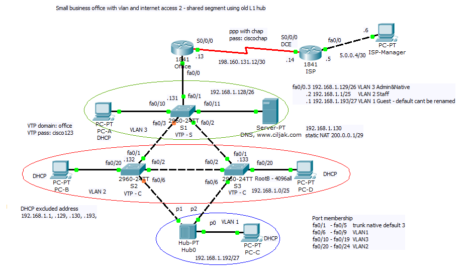
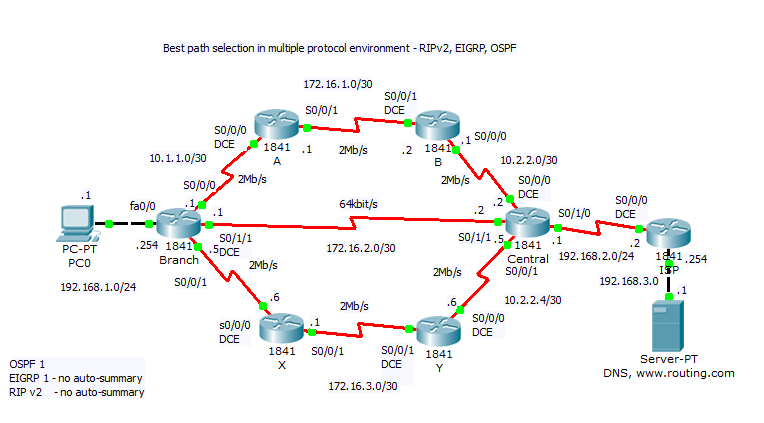
8. Small office configuration scenario with VLAN and internet access nr. 2

Small office network in our scenario separate hosts on 3 VLAN (1, 2 and 3). Because one part of network is really old we can here found shared segment with old L1 hub. Redundant link in switched topology introduced between S2 and S3 must be monitored with STP. 

Scenario consist of:

  • PPP link with CHAP authentication between Office and ISP router

              Office part of config:

                username ISP password 0 ciscochap

                interface Serial0/0/0
                ip address 198.160.131.13 255.255.255.252
                encapsulation ppp
                ppp authentication chap

             ISP part of config:
                 username Office password 0 ciscochap

                  interface Serial0/0/0
                  ip address 198.160.131.14 255.255.255.252
                  encapsulation ppp
                  ppp authentication chap
                  clock rate 2000000
 
  • NAT with PAT on S0/0/0 for inside hosts internet access
     ip access-list standard NAT
     permit 192.168.1.0 0.0.0.255
     ip nat inside source list NAT interface Serial0/0/0 overload
     
  • static NAT for local server 
     ip nat inside source static 192.168.1.130 200.0.0.1 
  • DHCP for appropriate LAN clients
     DHCP excluded address
              192.168.1.1, .129, .130, .193,

    ip dhcp excluded-address 192.168.1.1
    ip dhcp excluded-address 192.168.1.129
    ip dhcp excluded-address 192.168.1.130
    ip dhcp excluded-address 192.168.1.193
    ip dhcp excluded-address 192.168.1.131
    ip dhcp excluded-address 192.168.1.132
    ip dhcp excluded-address 192.168.1.133
    !
    ip dhcp pool VLAN3
     network 192.168.1.128 255.255.255.192
     default-router 192.168.1.129
     dns-server 192.168.1.130
    ip dhcp pool VLAN2
     network 192.168.1.0 255.255.255.128
     default-router 192.168.1.1
     dns-server 192.168.1.130
    ip dhcp pool VLAN1
     network 192.168.1.192 255.255.255.224
     default-router 192.168.1.193
     dns-server 192.168.1.130
     
  • router on a stick inter VLAN communication on Office router
    interface FastEthernet0/0
     no ip address
     duplex auto
     speed auto
    !
    interface FastEthernet0/0.1
     encapsulation dot1Q 1
     ip address 192.168.1.193 255.255.255.224
     ip nat inside
    !
    interface FastEthernet0/0.2
     encapsulation dot1Q 2
     ip address 192.168.1.1 255.255.255.128
     ip nat inside
    !
    interface FastEthernet0/0.3
     encapsulation dot1Q 3 native
     ip address 192.168.1.129 255.255.255.192
     ip nat inside
     
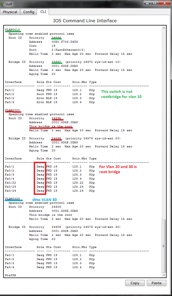
  • S3 rootBridge selection for STP
        spanning-tree vlan 1-3 priority 4096
     
  • VTP configuration with S1 acting as VTP Server propagating VLAN configuration to entire network
       VTP domain: office
       VTP pass: cisco123
       VTP-server – S1, VTP-Client S2, S3
     
  • subnetting with VLSM
      192.168.1.129/26 VLAN 3 Admin&Native
      192.168.1.1/25     VLAN 2 Staff
      192.168.1.193/27 VLAN 1 Guest – default cant be renamed
     

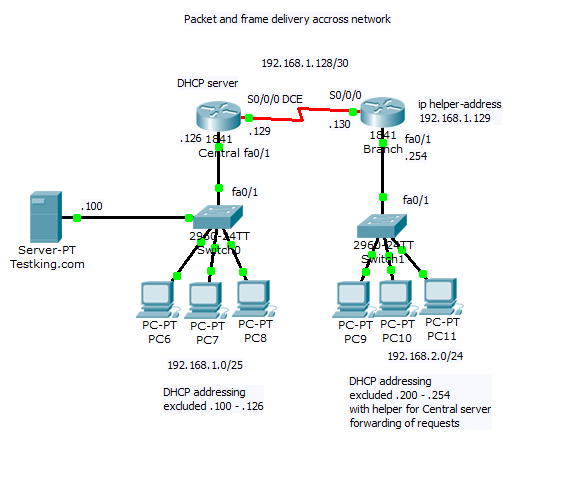
Preconfigured scenario can be obtained from here (PKT 5.2 or above you need). Topology diagram for scenario is


7. Small office configuration scenario with VLAN and internet access nr. 1

This scenario focus on:

  • host separation on appropriate VLAN
    fa0/1.3 192.168.3.1/24     vlan 3 Students
             .6 192.168.6.1/24     vlan 6 Staff
             .9 192.168.9.1/24     vlan 9 Farm
             .12 192.168.12.1/24 vlan 12 Admin&Native
  • inter VLAN communication with router on a stick scenario
    interface FastEthernet0/1
     no ip address
     duplex auto
     speed auto
    !
    interface FastEthernet0/1.3
     encapsulation dot1Q 3
     ip address 192.168.3.1 255.255.255.0
     ip nat inside
    !
    interface FastEthernet0/1.6
     encapsulation dot1Q 6
     ip address 192.168.6.1 255.255.255.0
     ip nat inside
    !
    interface FastEthernet0/1.9
     encapsulation dot1Q 9
     ip address 192.168.9.1 255.255.255.0
     ip nat inside
    !
    interface FastEthernet0/1.12
     encapsulation dot1Q 12 native
     ip address 192.168.12.1 255.255.255.0
     ip access-group ADMIN in
  • basic admin VLAN security
    ip access-list standard ADMIN
     permit host 192.168.12.10

    interface FastEthernet0/1.12
     encapsulation dot1Q 12 native
     ip address 192.168.12.1 255.255.255.0
     ip access-group ADMIN in
  • DHCP with first nine excluded address
    ip dhcp excluded-address 192.168.3.1 192.168.3.9
    ip dhcp excluded-address 192.168.6.1 192.168.6.9
    !
    ip dhcp pool VLAN3
     network 192.168.3.0 255.255.255.0
     default-router 192.168.3.1
     dns-server 192.168.9.254
    ip dhcp pool VLAN6
     network 192.168.6.0 255.255.255.0
     default-router 192.168.6.1
     dns-server 192.168.9.254
  • DNS server on host in VLAN 9 with IP 192.168.9.254/24
     
  • static NAT translation for server
    ip nat inside source static 192.168.9.254 200.0.0.1 
  • NAT with overload for private host accessing internet
     
    ip nat inside source list NAT interface Serial0/0/0 overload

    ip access-list standard NAT
    permit 192.168.3.0 0.0.0.255
    permit 192.168.6.0 0.0.0.255
     
    Preconfigured scenario can be obtained from here (PKT 5.2 or above you need).
    Topology diagram of descreibed network is on next picture. Host VLAN assignment is marked with configuration description


6. OSPF DR and BDR slection in multiaccess network segment examination lab.

Multi access networks create challenge for OSPF because:

a) create multiple adjacencies (one adjacencies for every pair of router)

b) extensive flooding of LSA – link state advertisement

for n -routers it is n(n-1)/2 adjacencies.

Because link-state protocols flood their link state packets during cold start or when there is a change in the topology possible solution is election of DR designated router.

DR – designated router in multi access network topology act as collector and distributor for LSAs. A BDR – backup designated router is elected in case the designated router fails. All other router become DROthers. Instead flooding LSA to all routers in multi access network, DROthers only send their LSAs to the DR and BDR using multicast address 224.0.0.6. The DR use multi access address 224.0.0.5. And the result is that only DR router flood all the LSAs in multi access network.

How are DR/BDR elected?

DR and BDR are elected this way:

1) DR – router with highest OSPF interface priority

2) BDR – router with second highest ospf priority

3) If ospf interfaces priorities are equal (default 1)., the highest router ID is used to break the tie.

To observe result of DR and BDR election results and neighbor adjacencies creation you can use

#show ip ospf neighbor

or per interface base

#show ip ospf interface fa0/0 (state, who is DR and who is BDR – their IPs).

When are DR and BDR elected?

Election take place as soon as the first router with ospf enabled interface is active on multi access network (powered in and network command is placed). When DR is elected, it remains DR until:

  • DR fails
  • OSPF process on DR fail
  • the multi access interface on DR fails

When DR fail BDR assume their role and election is held to choose new BDR.

When you will that router you want become DR and BDR (if boot first with not highest router ID or interface priority, first election can select wrong router as DR and BDR):

  • boot DR first, followed by BDR and next all other
  • shut down all interfaces on all routers and now use no shutdown on DR, then BDR and then on all others

How to change ospf interface priority?

Selecting right routers to become DR and BDR is crucial because their are collectors of all LSAs and its important to have sufficient CPU and memory capacity. Better control for election process as use router-ID for tie breaking is use

r(config-if)#ip ospf priority {0 to 255}

  • default is 1
  • 0 make router ineligible to became DR or BDR
  • router with highest interface priority – DR, second highest – BDR

Our preconfigured lab let you examine DR and BDR election process, you are encouraged introduce new physical links as  you can see in next pictures from their creation. An show ip route  show you best path selection when ospf as routing protocol is on use. Please remember how OSPF select preferred path, cisco ospf implementation use bandwidth. Cisco IOS uses the cumulative bandwidth of the outgoing interfaces from the router to the destination network as the cost (cost is associated with output side of each router interface and is ospf metric).

  1. Preconfigured scenario for our examination is here (PKT 5.2 or above is required) in their begining topology.

For best route selection process from network 200.2.0.0/24 PC0 to Server0 in network 200.1.0.0/24 use command show ip route on A-4 and B-1 routers. How are cumulative bandwidth increased in path introduced in routing table (best path to destination network) and DR, BDR election process is described next (click for better view).

2. In our network introduce shared segment between A-3 and B-3 router – this PKT lab is here.

New path with lower cost will be preferred for packet delivery (examine route introduction for network 200.1.0.0./24 in router A-4). For DR selection in shared network segment introduced in this scenario was for marked interface used ip ospf priority 128 (interface command).

How is new metric (4) calculated and output form show commands follow

3) Our last scenario introduce new path that will be best (lowest cumulative cost of outgoing interfaces). But we must adjust our subnet range from /29 mask to new /28 and introduce new network commands network 90.0.0.0 0.0.0.15 area 0 to accommodate our experiment. You are encouraged collect output from show commands and compare them against your theoretical results.

Final configuration for our lab can be obtain here (as earlier PKT 5.2 or above is required).

Explanation of DR, BDR selection and cumulative bandwidth calculation for best path is on next picture, Router -IDs are included in picture (no lo interface and router -id command was issued on any router – then higher ip of any active interface is used for ospf router-ID derivation).

Output from show ip route entered in router A-4 is


5. Reconstruction discovered network topology along Activity 8.1.2 (CCNA Exploration)

During me preparation for CCNA examen there was some challenges. One from it was discovering hidden network topology in CCNA Exploration course 4. chapter 8. Network troubleshooting with name Activity 8.1.2.

First big deal is make telnet sessions to devices obtained from local pc configuration (IPs of appropriate default gateways). Next you must show cdp neighbors or cdp neighbors detail and access L2 discovered neighbor switches for examination of VTP status, STP root bridge election and port states in stable state (converged network).

If you go around mentioned process you will obtain this topology diagram:

Or if you will in some compact form it look like this

Reconstructed scenario along me discovery can be obtain from here (PKT 5.2 or above).


4. Best path selection in multiple protocol environment with – RIPv2, EIGRP and OSPF

Dynamic routing protocol can decrease administrative overhead in large network environment. But what path will be selected for data traveling from point A to point B. Today published scenario will take closer look at path selection process in „academic“ multi protocol environment. 

Routing protocols that we can found in intra domain routing environment can be break down into two distinct category.

1. Distance vector routing protocols (RIPv1, Ripv2, IGRP, EIGRP) – advertisements about remote network are periodic, full or only affected parts of routing table (routing by rumor principe) – route is propagated as „route sign“ network „198.120.24.0/24“ and path to „serial0/1/0 or next hop 198.20.0.4/30“.

2. Link state routing protocols (OSPF, IS IS) – after link state data flooding at startup or after trigger (change in network environment) is created independently in appropriate router full network topology (OSPF use Edgar Dijkstra Shortest path first algorithm for it).

Routing protocols use for path selection and their next routing table introduction their own mechanism for metric marking. Our lab use 3 networking protocol, but to routing table are introduced only route with minimal Administrative Distance AD (say about trustworthiness appropriate routing protocol -. RIP 120, EIGRP internal route 90 and OSPF 110). Please if you will see route from intended routing protocol configure in testing environment routing protocols in this manner: 

a) RIPv 2 routing – and examine path selection – it will be with minimal hop count Branch to central

b) OSPF routing – minimal bandwidth is preferred – in our scenario are two equal path possible Branch – A – B – Central or Branch – X – Y – Central

c) EIGRP routing (cisco proprietary with maximum trustworthiness) – composite metric (default bandwidth and delay are used for calculation) will also cost load balancing between two mentioned path

Preconfigured scenario in cisco packet tracer 5.2 or above is here. Topology for testing scenario is

Output from #show ip route on Branch router with EIGRP route introduced in routing table }as mentioned earlier because this routing protocol has minimal AD 90 can be assumed as more trustworthy|.

Short look at Branch router interfaces and routing protocols config follow


3. Internet connection for small office with VLAN

This scenario is extension of article 1 where we have enabled internet access for our simple home or small office network. Our scenarios focus only proper connectivity without any access lists for adding local office policy.

For expecting work of this network you must:

  • configure VTP and VLAN
  • set STP 802.1D priority (STP about)
  • inter VLAN communication in router on a stick scenario
  • default route to ISP and static route pointing to Branch
  • PPP encapsulation on local loop to ISP central office
  • basic access passwords for network devices in topology
  • select proper cabling 
  • configure end devices with static or DHCP added IP and DNS
  • enable and adjust www, DNS, TFTP services
  • assign address from suggested networks

Training topology (configured PKT 5.2 lab)

VTP and VLAN on Staff switch is

STP configuration Admins and Staff sw is

   spanning-tree vlan 1,10 priority 24576

   spanning-tree vlan 20,30 priority 28672
 
Appropriate show command issued on Staff switch lead to expected root bridge election and port roles and states

Router interfaces was configured as it is listed in output Branch#show IP interface brief

Routers running configuration is:
 
hostname Branch
!
enable secret 5 $1$mERr$9cTjUIEqNGurQiFU.ZeCi1
!
ip dhcp excluded-address 172.16.20.224 172.16.20.254 address excluded from DHCP pool
!
ip dhcp pool StaffLAN                                 DHCP pool configuration 
 network 172.16.20.0 255.255.255.0
 default-router 172.16.20.254
 dns-server 172.16.10.253
!
username ISP password 0 pppcisco      access password for oposite end of ppp link used during chap 3 way handshake
!
no ip domain-lookup   router will not interpret incorrectly typed commands as domain names
!
interface FastEthernet0/0   
 no ip address
 duplex auto
 speed auto
!
interface FastEthernet0/0.20
 encapsulation dot1Q 20
 ip address 172.16.20.254 255.255.255.0
 ip nat inside  marking interface inside „local“ for NAT
!
interface FastEthernet0/1  address was removed or not configured on interface divided on subinterfaces in router on a stick
 no ip address
 duplex auto
 speed auto
!
interface FastEthernet0/1.10
 encapsulation dot1Q 10 native   native keyword mark VLAN used for untagged traffic – from default 1 moved to 10
 ip address 172.16.10.254 255.255.255.0
 ip nat inside   marking interface inside „local“ for NAT
!
interface FastEthernet0/1.30
 encapsulation dot1Q 30
 ip address 172.16.30.254 255.255.255.0
 ip nat inside     marking interface inside „local“ for NAT
!
interface Serial0/0/0
 ip address 198.160.130.5 255.255.255.252
 encapsulation ppp     encpasulation and authentification on ppp link
 ppp authentication chap
 ip nat outside   marking interface as outside „local“ for NAT
!
interface Serial0/0/1
 no ip address
 shutdown
!
interface Vlan1
 no ip address
 shutdown
!
ip nat inside source list Allowed interface Serial0/0/0 overload  PAT with interface s0/0/0 overload command
ip nat inside source static 172.16.10.253 198.160.130.1   static NAT translation for connectivity to inside company web server from outside network
ip classless
ip route 0.0.0.0 0.0.0.0 Serial0/0/0   default route used for routing outgoing traffic
!
!
ip access-list standard Allowed         access list marking clients allowed for NAT translation
 permit 172.16.10.0 0.0.0.255
 permit 172.16.20.0 0.0.0.255
 permit 172.16.30.0 0.0.0.255
access-list 1 permit 172.16.10.0 0.0.0.255
!
line con 0
 exec-timeout 30 0
 password cisco
 logging synchronous
 login
line vty 0 4
 access-class 1 in
 exec-timeout 30 0
 password cisco
 logging synchronous
 login
!
end

On DNS, www.company.sk server are made these settings

DNS records


2. Packet and frame delivery

When data segment is encapsulated into packet appropriate PC must examine destination address when preparing frame creation. If destination IP is on same network as sending PC data are send to to appropriate host. Else data are sent to network interface that act as a default gateway.

This process use and-ing destination IP in binary format with binary format of network mask and next make comparation with configured network address. If they are unequal data are send to default gateway (MAC address of default gateway is set as destination address of frame). In this scenario you are encouraged to create PDU in simulation mode and examine packet delivery. Interesting are also PDU at appropriate protocol stack (Transport, network and data link layer).

Topology of our scenario is

Preconfigured scenario (PKT 5.2 or above).

When you toggle betw. realtime and simulation mode, interface will change to next picture

After appropriate time used for PDU propagation across network (and ARP caching for L2 encapsulation), PC11 can send frame to Branch fa0/1 interface that act as a default gateway. You can scroll event list and look at PDU emitted by PC11 after ARP process as it show next picture.


1. Enabling internet access with PAT for small office

Small office need acces to internet. Internal office network use 192.168.66.0/24 network rane and contain four clients with static preconfigured IP and DHCP range 192.168.66.100-200 (ip dhcp excluded-address 192.168.66.1 – .99 and 201.  – 254). Switching topology is without redundancy with Office 1841 router ast in router on a stick scenario. ISP is simulated by ISP router with remote www.cisco.com server.

Network topology:

Office server dns configuration that resolve name www.testking.com and www.cisco.com is configured:

Pc with static ip are configured:

Device configs are: (!!! Some ! was ommited from config!!!)

1) Switch S1


hostname S1
!
!
!
interface FastEthernet0/1
!
interface FastEthernet0/2
!
interface FastEthernet0/3
!
interface FastEthernet0/4
!
interface FastEthernet0/5
!
interface FastEthernet0/6
!
interface FastEthernet0/7
!
interface FastEthernet0/8
!
interface FastEthernet0/9
!
interface FastEthernet0/10
!
interface FastEthernet0/11
!
interface FastEthernet0/12
!
interface FastEthernet0/13
!
interface FastEthernet0/14
!
interface FastEthernet0/15
!
interface FastEthernet0/16
!
interface FastEthernet0/17
!
interface FastEthernet0/18
!
interface FastEthernet0/19
!
interface FastEthernet0/20
!
interface FastEthernet0/21
!
interface FastEthernet0/22
!
interface FastEthernet0/23
!
interface FastEthernet0/24
!
interface GigabitEthernet1/1
!
interface GigabitEthernet1/2
!
interface Vlan1
 no ip address
 shutdown
!
interface Vlan99
 ip address 192.168.66.253 255.255.255.0
ip default-gateway 192.168.66.254
line con 0
line vty 0 4
 login
line vty 5 15
 login
end
There are no VLAN configured – convinient only in very small network with full trustworthy environment.
 
2) Router Office
 
hostname Office
ip dhcp excluded-address 192.168.66.1 192.168.66.99
ip dhcp excluded-address 192.168.66.201 192.168.66.254
ip dhcp pool Office_LAN
 network 192.168.66.0 255.255.255.0
 default-router 192.168.66.254
 dns-server 192.168.66.252
username ISP password 0 pppcisco
interface FastEthernet0/0
 no ip address
 duplex auto
 speed auto
 shutdown
!
interface FastEthernet0/1
 ip address 192.168.66.254 255.255.255.0
 duplex auto
 speed auto
!
interface Serial0/0/0
 ip address 198.160.130.129 255.255.255.240
 encapsulation ppp
 ppp authentication pap
 ppp pap sent-username Office password 0 pppcisco
!
interface Serial0/0/1
 no ip address
 shutdown
!
interface Vlan1
 no ip address
 shutdown
!
ip nat pool PATforLAN 198.160.130.135 198.160.130.140 netmask 255.255.255.240
ip nat inside source list PATenabled pool PATforLAN overload
ip classless
ip route 0.0.0.0 0.0.0.0 Serial0/0/0 
!
ip access-list standard PATenabled
 permit 192.168.66.0 0.0.0.255
 deny any
!
line con 0
line vty 0 4
 login
!
end
 
3) ISP router
 
hostname ISP
!
username Office password 0 pppcisco
!
interface FastEthernet0/0
 ip address 200.0.0.2 255.255.255.252
 duplex auto
 speed auto
!
interface FastEthernet0/1
 no ip address
 duplex auto
 speed auto
 shutdown
!
interface Serial0/0/0
 ip address 198.160.130.130 255.255.255.240
 encapsulation ppp
 ppp authentication pap
 ppp pap sent-username ISP password 0 pppcisco
 clock rate 250000
!
interface Serial0/0/1
 no ip address
 shutdown
!
interface Vlan1
 no ip address
 shutdown
!
ip classless
ip route 192.168.66.0 255.255.255.0 Serial0/0/0 
!
line con 0
line vty 0 4
 login
!
end
 
Link between ISP and Office router is serial PPP line with older PAP authentication.
 
(!!! Some ! was ommited from config!!!)