1

16. CUCM 8 – Call hunt configuration

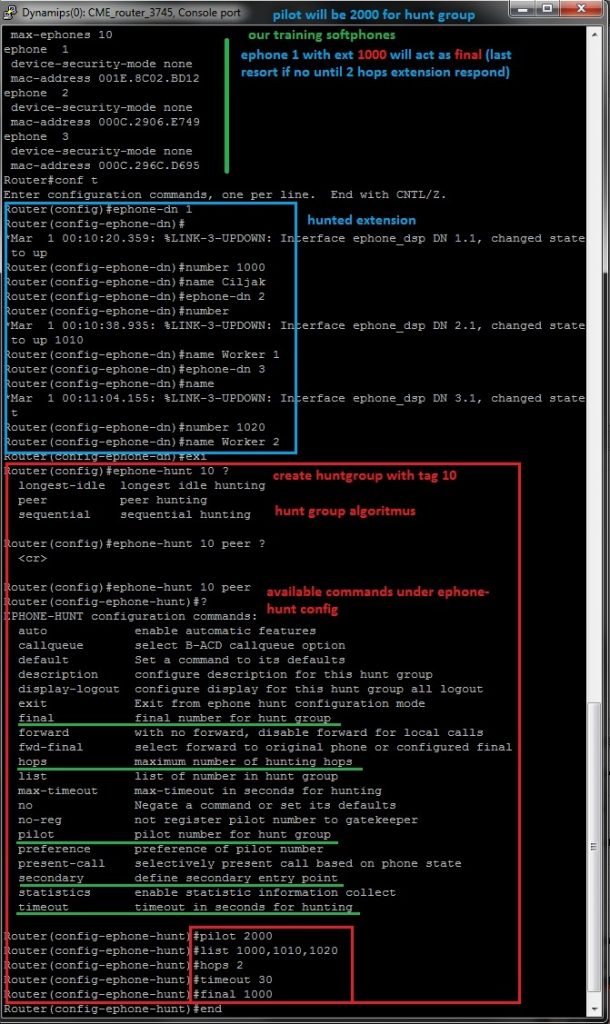
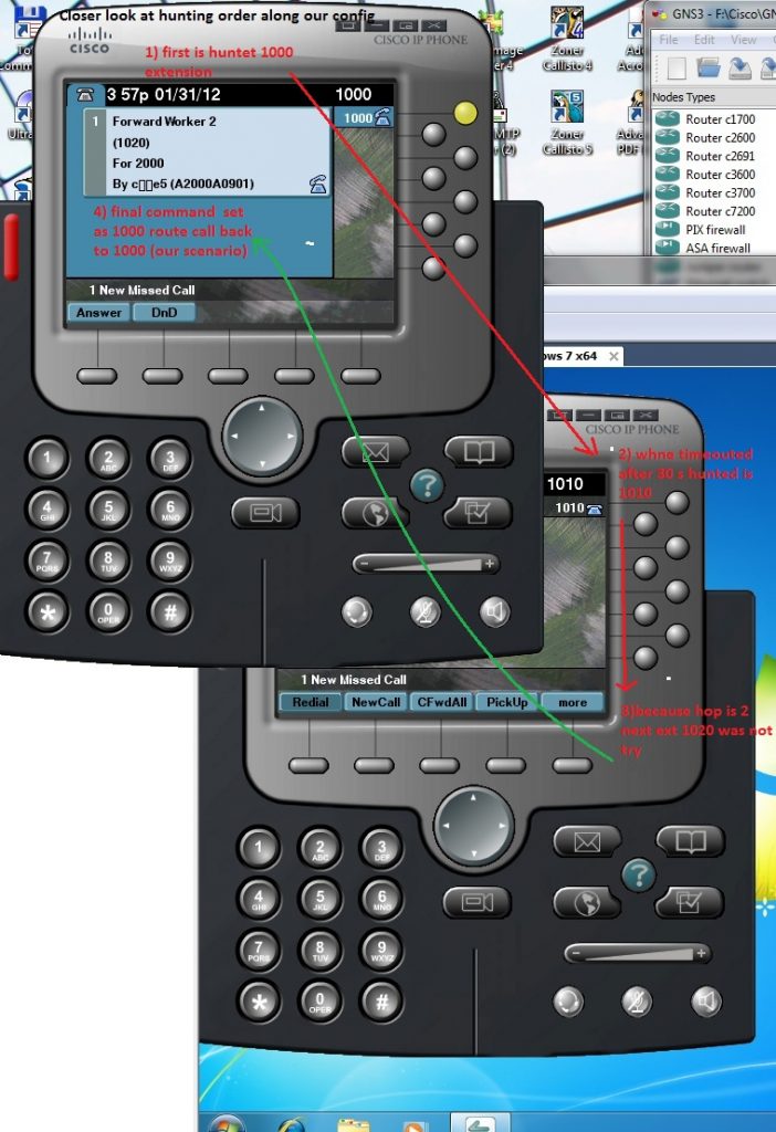
As it was in CUCME call hunt enable one hunt pilot number to distribute calls to members of hunt list. For reference please read our article http://www.cdesigner.eu/content/12-hunt-groups-how.

CUCM configuration for call hunt is more flexible and robust. During creation of hunt environment we going through this steps:

  1. Create line groups that contain hunted extensions (in our case 1000, 1001, and 1002)
  2. Create hunt lists that contain line group or groups
  3. Finally create and adjust hunt pilot

In this lab our goal will be create config that support this scenario.

Now we going to create line groups that specify hunting behavior – Line groups are added to hunt lists which select order during hunting through line groups. Finally associate hunt pilot to appropriate hunt list.

I) Line groups

  • create DNs for phones and associate them
  • in CM administration Call Routing>Route/Hunt>Line Group and add new
  • specify RNA (ring no answer) – time of each DN in line group will ring before no answer is reached and call is relayed to next DN in group
  • distribute algorithm: Top Down – each new call starts at the top of list, Circular – round robin fashion – new call starts at the next DN after previous used on call, Broadcast – all DNs ring simultaneously or Longest idle (number that was longest in On Hook state become ringing)
  • Hunt – options for call state (Busy, noan …), determine moving of call through line groups if they exist (our simple scenario has only one line group)
  • add DNs to line group (1000, 1001 and 1002) and save

After successful configuration new entry in line group list exist

II) Hunt list

  • go to Call Routing>Route/Hunt>Hunt list and add new
  • fill name and select CUCM group if it is not stand alone CUCM deployment as in our case – then save
  • in hunt list configuration – add line groups (line groups are top down processed please remember this fact – order in list is important) and save

III) Hunt pilot

  • Call Routing>Route/Hunt>Hunt pilot and add
  • specify hunt pilot number (3000 in our case)
  • select hunt list or lists
  • set Alerting name (displays on phones receiving calls by dialing hunt pilot number)
  • optionally set hunt forwarding (for our examination we first leave this field blank)

Our lab is configured to support call hunt on pilot number 3000. It is time to try our config. From phone with extension 1002 initiate call to hunt pilot nr. 3000. Cal is routed to first number 1000 in circular fashion (circular distribution algorithm). After 20s configured as no answer interval our phone receive ringing after next 20s. Caller phone receive noanswer signal because no forward option was configured.

Finally we adjust no answer forwarding in hunt pilot configuration menu.

Now is call processing handled so as it is described in firs picture with configuration goals. When any of extensions in line group does did not noanswer call is forwarding to its final destination number 2000 (it is a shared line in our training environment).


15. Extension mobility in CUCM v. 8.6

Extension mobility (EM) enable user log in to any phone in working environment and then obtain appropriate private configuration of their phone. This functionality is ideal in environments with moving workers.

EM is a phone service that must be enabled and apply user-specific device profile. But separate device profile must be made for all type of supported devices (7965 phone has 6 button but 7940 only two that must be properly accommodated).

Administrator has these options for logging behavior:

  • allow multiple logins – multiple logged in phone
  • deny login – when logged in one phone another reply with error until logout previews
  • auto-logout – only one logged in device in a time

How to enable EM in CUCM?

1) Activate cisco EM service. In serviceability web page – Tools>Service activation and select Cisco Extension mobility and Save.

2) Configure EM service parameters. In CUCM administration page go to: System>Service parameters and select appropriate server (our scenario is single server). Select Cisco extension mobility service from service drop-down.

Scroll to Clusterwide Parameters (force logout after maximum login time has expired, and timer number, login behavior.) Also numeric ID for user can be enabled or enable remember of last logged in user.

3) Add the EM service. Go to Device > Device settings > Phone services and add new. Give service appropriate name (EM_service) and to service field type: http://<IP_address_of_Publisher>:8080/emapp/EMAppServlet?device=#DEVICENAME#.

Make sure Enable is checked and optionally check Enterprise subscription (automatically subscribes all IP phones to EM service).

4) Create default device profile. In CUCM administration page go to Device > Device settings > Default device profile and add new. Select Product type (phone model we only have CIPC phones) and Device Protocol.

5) Create Device Profiles. Go to Device > Device settings > Device Profile and add new. Select phone model for particular user phone and enter name for that profile. Configure user specific settings: DN, Button and other parameters.

6) Subscribe Device profiles to the EM service. From Device Profile page choose Subscribe/Unsubscribe Services from links and click go. Chose EM service added previews and Next. Enter display name for EM service and ASCII version for phones with low resolution display. Click Subscribe and Save. Remember subscribe both Device profiles and IP Phones to EM service – user will be unable log out after he log in and device profile is applied.

7) Associate Users with device profiles. Go to User Management > End User Select user whom you want create profile associations or create new user. For user chose Device Profiles that should be associated to user (if more profiles selected one must be selected to use after logging into EM).

8) Enable EM for Phones. Go to Device > Phone and select appropriate phone which will serve for EM. In Extension Mobility selection check enable extension mobility box. Chose specific Device profile or currently configured device setting as in Log Out Profile. (log Out profile is configuration that is applied to phone when no-one is logged in. Often it is emergency or local capabilities.)

9) Subscribe Phones to EM service. In phone configuration page, choose Subscribe/ Unsubscribe Services. Chose EM service from Service pull-down. Enter the name that will appear on IP Phone.

For further reference please watch this video from youtube http://www.youtube.com/watch?v=M50sykfNe5I&feature=related


14. CUCM 8 – free sftp solution for backup on ubuntu 10.04 server

All application based elements of cisco unified communication platform offer disaster recovery system that enable backup and recovery after failure. Backup can be made to two devices. First option is tape device, second is secure FTP (sftp). Because we need cost saving solution in training environment we decided for open-ssh server on ubuntu server.

Cisco recommended steps for establishing backup on Cisco unified platform are here http://www.cisco.com/en/US/products/sw/voicesw/ps556/

products_configuration_example09186a0080ab9fc0.shtml.

Next steps expect basic unix system administration abilities. From ubuntu.com please obtain ideal LTS version of ubuntu server. At this time it is version 10.04 for 32 or 64 bit platform.

Next steps describe only necessary commands for CUCM backup account creation, open-ssh server install and change ownership and adding permission to modify content of user home directory.

Open-ssh server as sftp server on ubuntu step-by-step:

1) Create group for sftp access (optional) for further platform hardening – sudo groupadd sftpuser

2) Create user account for backup sudo adduser cucm_8 sftpuser and make password during user creation dialog

3) Change ownership of home directory sudo chown root.root /home/cucm_8

4) Alter permission for read and write to home directory of backup user sudo chmod 777 /home/cucm_8

5) Install open-ssh server  sudo apt-get install openssh-server

6) Test connectivity to sftp account from FileZilla client (or your preferred supporting secure mode) – transfer and delete file!!!


And another way look – from CLI of ubuntu server

Now is all prepared for CUCM Disaster recovery system setup. From administration menu select Disaster recovery system and type platform administration password.

After successful login we going to next menu

Before first backup disaster recovery system need create a backup device. There are two options, but in training environment is only one options, make a backup to sftp server (that we succesfully manage in previews steps).

And in adding dialog properly configure sftp access credentials – user, password and path to backup directory in backup server in our case it is /home/cucm_8/backup

In next step if verification of sftp server was without any errors we obtain this output

Our backup device have been successfully created and now it is right time make first disaster (our training of course :-)) backup. To backup dialog as you can guess lead this way

This choice open dialog for manual backup

Before backup begin we obtain warning about password for access of backup content like this

Our data now moving to sftp server in encrypted form (are not so easy to read in case of their interception).

When transfer completed  …

Also CUCM Disaster recovery system remember successfully made backup and generate this output in backup history .


13. Elimination reliance of CUCM on DNS service

DNS name resolution is needed in voice network if DNS is in use. DNS lookup process must occur before any signaling occur. As result we can expect delay or in worst failure of DNS system on network environment lead to failure in voice placing. Conclusion is DNS is not recommended for use in voice network.

Closer look on protocolar data flow in network with DNS is on next picture. For drawing topology diagram you can obtain appropriate stencil for Ms Visio from cisco page http://www.cisco.com/web/about/ac50/ac47/2.html.

But network environment in voice VLAN can be clean from DNS PDU as you can see on picture that demonstrate network with eliminated DNS.

Now you can ask: What is the way how to eliminate reliance of CUCM on DNS?

Default installation of CUCM (as it show next picture) list hostname of CUCM server (Publisher or subscribers) in database field but not real IP address. To change these value we must select appropriate CUCM server from system administration menu and replace name with IP address (System -> Server (then appropriate server)).

From list our cluster servers (in my case it is stand alone CUCM server) select appropriate server and open it that lead to next window.

But in CUCM database is another reliance on DNS system. Phone service URLs use name of server against appropriate IP. We must change it this way. Go to System -> Enterprise parameters and scroll down to Phone URL parameters and Secure phone URL parameters. Change appropriate DNS names to appropriate IP address (in our training environment it will be 172.16.0.20).

In this two block of config change host name of CUCM to its IP address.

Now is our voice network much more independent from DNS failure. But keep in mind that there is also reason to stay on DNS based network model for voice segment. That is when you expect change in network addressing plan, names are more stable as IP address.


12. Hunt groups how to

Hunt groups enable set one phone number (this number is refered as pilot number) as distributor of call to extensions defined in number list. Hunt group selection algorithm defines who receive next call in list. Our lab will show you how to configure simple hunt group on Cisco Unified CME.

Basic terms bounded with hunting number in list from pilot number are:

  • pilot number – ephone-DN that is dialed to reach a hunt group. (optionally keyword secondary)
  • algorithm type – method used to select which phone in hunt list should ring next,
  • list of member – group of ephone-DN that belong to the hunt „pool“,
  • hops – number of extensions that algorithm will try to ring before going to the final number,
  • timeout – in seconds – how long will ring a extension in hunt list before moving to the next extension selected by algorithm,
  • final number – number that is tried last after the number of hops has been exceeded

For hunt group creation is used ephone-hunt <Tag> configuration command. Tag can be number from 1 to 100.

For selection of next ringing phone in hunt group in Cisco Unified CME can be selected these algorithm:

  1. Longest idle – ring phone that was longest idle
  2. Sequential – rings extensions in exact order as was configured in list
  3. Peer – circular fashion – next ringed extension is in right position in list against previews ringed.

Our scenario consist of three ephone with unique extensions 1000, 1010 and 1020. All numbers are in hunt list. For ephone-hunt <Tag> algorithm we select nr. 10. As a pilot number had been selected 2000. Final destination after ringing number in list after hop 2 is first extension 1000. 

Next picture show configuration commands and appropriate options for select

Closer look at call to hunt pilot and mechanism of selection ringing phone by hunt algorithm describe next two pictures:

First number in hunt list is extension 1000 next hunted  number is right from 1000 (it is 1010) because peer (circular) algorithm was configured using ephone-hunt 10 peer command. When hops reach 2 (two ringed extensions) final number 1000 take ringing line.


11. Cisco unified communication manager 8.6 autoregistration for ephones

CUCM (Cisco unified communication manager) 8.6  is application based (run on isolated Linux OS RedHat)  comprehensive communication platform that support features for high deployment scenario up to 40 000 user per cluster. Further reading about development products from communication manager line can be found on article http://en.wikipedia.org/wiki/Cisco_
Unified_Communications_Manager
.

Our training lab will run CUCM 8.6 on environment of VMware workstation 8 (or later) – for simulation must be dedicated for this machine 2G RAM and 1 CPU core as a minimum. How to install CUCM from installation image pleas read 

http://www.computerfreetips.com/Cisco-Call-Manager-CUCM/Cisco-CUCM8-install-vmware.html.

First important thing is that administrative web environment consist from 5 interfaces as you can see from next picture 

Auto registration is disabled by default against default behavior of small brother CUCME (up to 400 in ISR G2 routers older ISR routers support up to 250 clients).

Next steps enable auto registration on single CUCM installation environment (act as single publisher with no subscribers for redundancy).

1) Enable services important for work – CM service and TFTP (all is disabled by default). This is done by Cisco unified serviceability in web interface.

Select these services and apply

2) Check settings under system – CM groups and default group created during install

3) Enable auto registration under Communication manager from same section system

As reference for configuration please refer to video of Kewin Wallace on youtube http://www.youtube.com/watch?v=rGeh8zsm890&list=
PLCDD735A54A71D3CC&feature=mh_lolz


10. Paging

Paging enable to broadcast voice message to ephones. We can look at paging as one-way intercom. Difference between intercom and broadcast is that paging broadcast message to multiple or all phones.

A phone can be assigned only one paging ephone-dn but you can assign paging groups to include multiple ephone-DNs.

Paging can be configured as:

1) Unicast – is limited to max 10 receiving devices (high traffic volume ) – all streams contain same information that waste resources.

2) Multicast – scale well, need to configure UDP port number for multicast stream (default is 2000 UDP).

Our training lab will use extension 6000 for paging ephone-dn and for multicast use 239.1.1.1 port 2000 (224.0.0.0 – 239.255.255.255 except 224.x.x.x MoH).

Example of CLI config:

configure terminal

ephone-dn 5

number 6000

paging ip 239.1.1.1 port 2000

exit

ephone 1

paging-dn 5 multicast

ephone 2

paging-dn 5 multicast

ephone 3

paging-dn 5 multicast

end

Great command that can be used for examination only ephone part of running-cofigu is

Now we are able call to paging extension 6000 and make a call

Now you can feel one-way intercom – when we are „through“ voice is broadcasted from subscribed devices speaker as it is indicated with green light on speaker.

When more granular control over paging members is expected there can paging group help. How to do it follow next:

1) Make appropriate paging ephone-dn one per member of paging subgroup

ephone-dn 5

number 6000

paging ip 239.1.1.1 port 2000

ephone-dn 6

number 7000

paging ip 239.1.1.2 port 2000


2) Group appropriate paging-dn to wished paging groups – we use only one group associated with number 7777 that will broadcast voice to all of our ephones

ephone-dn 7

number 7777

paging group 5 6


3) Assign paging-dn for appropriate ephones

ephone 1

paging-dn 5 multicast

ephone 2

paging-dn 5 multicast

ephone 3

paging-dn 6 multicast

(Ephone 1 and 2 are paged from ephone-dn 5 number 6000 and ephone 3 belong to another paging group with ephone-dn 6 and call extension 7000. But all phones can be paged in same time when we make call to extension 7777 that is paging group binding ephone-dn 5 and 6 together.)


0 Preparation of basic VoIP environment with CME

Baseline for our first training environment created with support of GNS is  www.brainbump.net/tutorials/voice/CMEusingGNS3.htm . Testing environment will use cloud component mentioned in earlier topics for interconnection virtual and real pc environment. Me home network use 172.16.0.0/24 private addressing scheme. For training pc where will run also software IP communicator use static assigned 172.16.0.10/24 IP. CME routers fa0/0 interface use 172.16.0.20/24 IP and for future use is planed 172.16.0.15/24 (second sw IP communicator – functionally equal to cisco 7970 ephone) on VMware environment.

Our project settings show next picture – for smoother transfer of configs check to save configs and nvrams.

Configuration of hosting (real) computer local stack is

GNS3 training environment is prepared and if you will you can add some eyecandy

For our first test we can use simple way how to setup telephony-service on router (but only for quick setup, this way is not so flexible as finetunnig of all parameters of telephony-service).

We also need sw ephone, installation is

When all is prepared for first test, our ephone will be able to register with CME router acting like a voice gateway. Auto registration was enabled during telephony-service setup for us automatic.

Next picture show you closer look at registering ephone and at screen with button 1 assigned ephone-dn with number 555 (but configuration ephone-dn, ephone-s, buttons and all things associated with VoIP in branch LAN and next with configuration of voice gateways and call legs you can expect in next articles on our web).


GNS3 for our VoIP home training lab

Basic simulation element for our sw based home training lab will be GNS 3 simulator. But question is, what it is GNS3 simulator. Best description we found at www.gns3.org: “ GNS3 is a FREE graphical network simulator that allows simulation of complex networks without the need to purchase network hardware.  

There will arisen second questions: Is it free? And answer is yes and noapplication is free bud as they say: “ Users have to provide their own IOS/IPS/PIX/ASA/JunOS to use with GNS3. GNS3 does not include IOS images – these are copyrighted and are the property of Cisco Systems and other copyright holders. “ , www.gns3.org, 4.12.11

We will assume that you have appropriate IOS images from your cisco pages and are correctly licensed now.

Great video about obtaining GNS3 and take basic setup is provided by project homepage: http://www.gns3.org/2011/09/video-how-to-download-install-and-get-working-gns3/. One of the most important thing is run virtualized IOS and calculate Idle PC value that are important for resource management of hosting PC. If you ignore this step, GNS simulator with only one running router will consume your whole pc computing resources (full load your system).

Before we start with basics voice simulations, i will introduce one great simulation component that enable us interconnect virtualized network environment with existing resources on our pc-s ore our home network.

This component is cloud and can be added this way

For proper configuration right click on cloud in topology pane and

In open dialog select instance name C1  and scroll your physical interface (network car of hosting pc) – in this case there were 6 interfaces (look at next 2 pictures).

Then click add button and next ok.

With interconnected hosting (your) PC and simulation environment (that is in fact not a simulation but Virtualization for run real IOS – but switching concepts are poorly implemented) you can try SSH access to router as you can see on next photos. But prerequisite is that you from CCNA know how to enable SSH access to VTY line of your router with appropriate user account and local or radius authentication.

Config of router was

hostname c2691_k9
!
boot-start-marker
boot-end-marker
!
enable secret 5 $1$e.aD$bBCjuv86TM6sbFKb7Spvm0
!
no aaa new-model
memory-size iomem 5
ip cef
!
no ip domain lookup
ip domain name ciljak.com
!
!ip ssh authentication-retries 2
!
interface FastEthernet0/0
 ip address 172.16.0.5 255.255.255.0
 duplex auto
 speed auto
!
interface FastEthernet0/1
 ip address 192.168.1.1 255.255.255.0
 duplex auto
 speed auto
!
!
no ip http server
no ip http secure-server
 
!
control-plane
!
line con 0
 exec-timeout 0 0
 logging synchronous
line aux 0
line vty 0 4
 login local
 transport input ssh
line vty 5 935
 login local
 transport input ssh
!
!
end
 
Some command was added automatically, that must be keep in you mind and some ! was omitted.


9. Call parking

Call parking enable to place call in „parked“ slot using unassigned ephone-DN and then resume the call from any cisco phone. Call park is the same functionality as hold bud call placed on hold can be resumed only from local phone. You can look at parking the call as extension of hold call.

Unused ephone-dn or ephone-DNs must be configured for parking slot.

Our lab reserve ephone-dn 7 and 8 as parking slots. Park slot on ephone-dn 8 is reserved for extension 1000 (ephone 1) with command entered under ephone-dn config.

Reserved-for options allocate park slot for specific extension (reserve it).

The timeout options configure timer that can help prevent people from parking calls and then forgetting about them.


Appropriate CLI commands are

ephone-dn  7

 number 8000
 park-slot
 name Park slot I.
!
!
ephone-dn  8
 number 8001
 park-slot reserved-for 1000 timeout 120 limit 2
 name Park slot II.
 
 
Output from CLI is

Now is time to try our configuration. call is placed from 1020 (ephone 3) to 1000 (ephone 1). Park softkey is shy under more softkey.

When we have been parked call for a while our screen look like this

Call is on parked slot and now is time to pickup them by dialing to park slot number 8001 from as example extension 1010 that is ephone 2 (this slot is reserved for ephone 1).

At end is call obtained from parking slot and will continue.