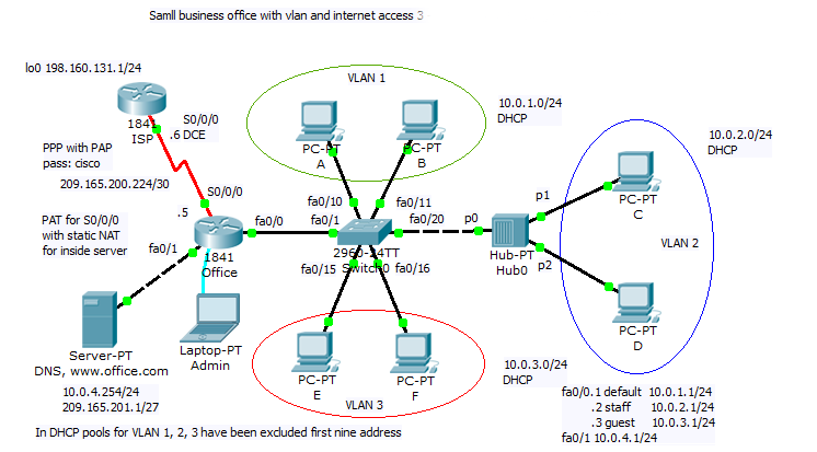
9. Small office configuration scenario with VLAN and internet access nr. 3


New network scenario consist of one branch router with default routing to ISP. WAN internet access use PPP serial link with old PAP authentication. Office hosts are separated in 3 VLAN. Vlan 1 remain default, VLAN 2 is staff and for guests is reserved guest VLAN 3. Administrator use Admin Laptop for direct console CLI access. Switched network remain very simple, there is only one switch extended with old hub Hub0 (clients C and D share same subnet but also same collision domain).
- Serial link with PPPencapsulation and PAP authentication:
On Office router:
username ISP password 0 cisco
On ISP router:
username Office password 0 cisco
- loop back interface on ISP router for testing remote connectivity
interface Loopback0ip address 198.160.131.1 255.255.255.0
- static route in ISP pointing to Office inside global (public) address
ip route 209.165.201.0 255.255.255.224 Serial0/0/0
- default routing to ISP
ip route 0.0.0.0 0.0.0.0 Serial0/0/0
- static NAT and NAT with interface serial 0/0/0 overload PAT for local hosts internet connectivity
ip nat inside source list NAT interface Serial0/0/0 overloadip nat inside source static 10.0.4.254 209.165.201.1ip access-list standard NATpermit 10.0.0.0 0.0.255.255
- DHCP address assignment for all VLAN clients
ip dhcp excluded-address 10.0.1.1 10.0.1.9ip dhcp excluded-address 10.0.2.1 10.0.2.9ip dhcp excluded-address 10.0.3.1 10.0.3.9!ip dhcp pool VLAN1network 10.0.1.0 255.255.255.0default-router 10.0.1.1dns-server 10.0.4.254ip dhcp pool VLAN2network 10.0.2.0 255.255.255.0default-router 10.0.2.1dns-server 10.0.4.254ip dhcp pool VLAN3network 10.0.3.0 255.255.255.0default-router 10.0.3.1dns-server 10.0.4.254
- inter VLAN routing with router-on-a-stick
interface FastEthernet0/0no ip addressduplex autospeed auto!interface FastEthernet0/0.1encapsulation dot1Q 1 nativeip address 10.0.1.1 255.255.255.0ip nat inside!interface FastEthernet0/0.2encapsulation dot1Q 2ip address 10.0.2.1 255.255.255.0ip nat inside!interface FastEthernet0/0.3encapsulation dot1Q 3ip address 10.0.3.1 255.255.255.0ip nat inside
Interesting part of this scenario is shared network segment using hub for extension switched LAN. Our interests is in switching table of Switch0. We can ask: how will be mac-address-table finally populated? At first we must ping devices on network that will populate switching (mac.address-table).Example of ping from Office router to all network device:
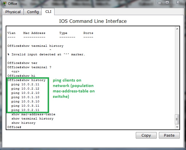
Our Switch0 mac-address-table look like this
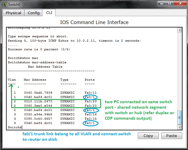
Two or more PC assigned to one switch port in address table (switching table) is example of shared network segment connected on port fa0/20. But we can not examine from this that this is next switch or hub (you must use CDP show cdp neighbors or show interface fa0/20 that is in full or half duplex mode).
Switch port assignment to appropriate VLAN examine show vlan brief command issued on switch0
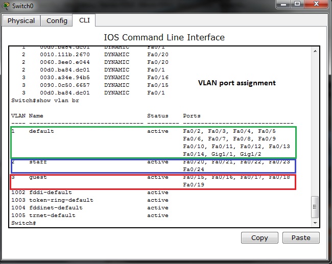
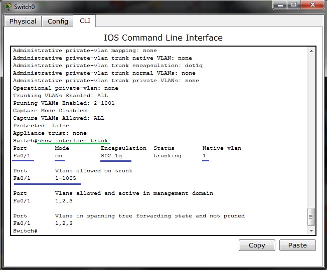
Switch port fa0/1 is excluded from list because is trunk port connecting switch and Office router in router-on-a-stick inter vlan. For port fa0/1 state examination we can use show interface fa0/1 switch port CLI command
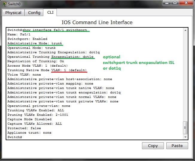
Native (default) VLAN is 1 that is default switch out of box configuration and trunk encapsulation is dot1q.
Same command issued on access port fa0/20 result in output:
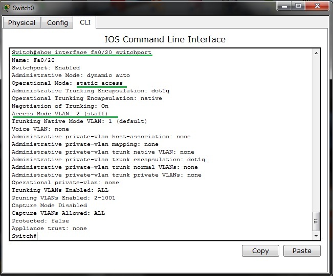
Port is bounded with VLAN 2 as you can see on topology diagram and from show vlan brief CLI command output.
Please remember that there is also one show command for trunk ports examination – it is show interface trunk