14. Wrong default route propagation in OSPF enabled network


Default route introduce ultimate outgoing interface for L3 PDU from our network. Most common use is in stub-networks where is only one interface pointing to outside network (in this case is no need for load balancing between two or among ISPs interfaces). Instead of routers having to store routes for all of the networks in the internet, they can share a single default route to represent any network that is not in the routing table.
In small office networks is static routing and manual default route settings in use but in large network or in much more flexible network scenarios are dynamic routing protocol introduced.
Static default route can be propagated from router where command ip route 0.0.0.0 0.0.0.0 interface/IP_of_next_hop to all other routers in network.
How to enable default route distribution to network with most common IPv4 routing protocols?
1) Configure static default route on router that act as network boundary to ISP network with command:
ip route 0.0.0.0 0.0.0.0 interface/IP_of_next_hop
2) Default static route needs to be advertised to all others routers that use dynamic routing protocols
- for RIP1/2 use router command: default-information originate
- for EIGRP use router command: redistribute static
- for OSPF use router command: default-information originate
But what is happen when wrong default route is introduced in network topology? How troubleshoot problem with wrong default static route? We going to explore how this condition affect our production network and how to fix it.
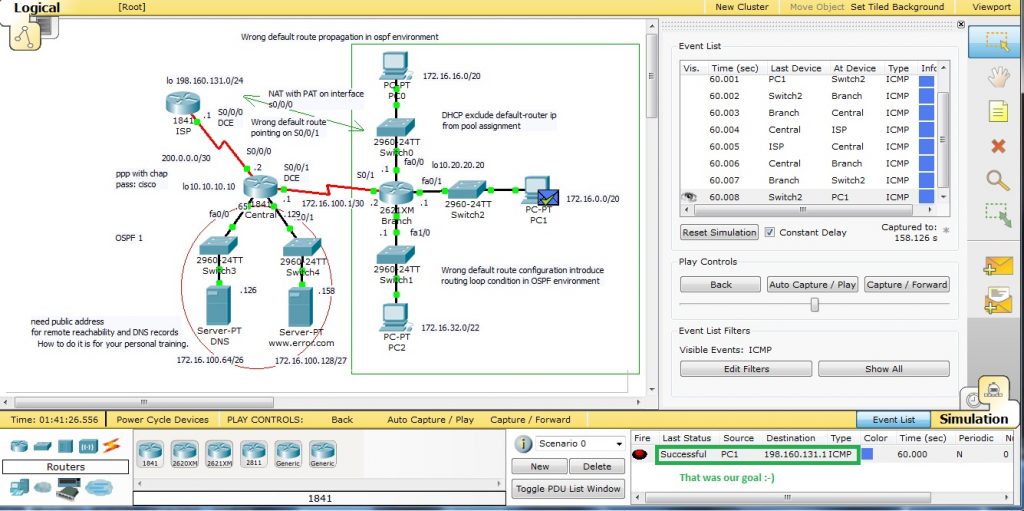
Preconfigured scenario in cisco packet tracer 5.2 or above can be obtained from here. Small office network in this scenario look like this
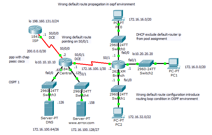
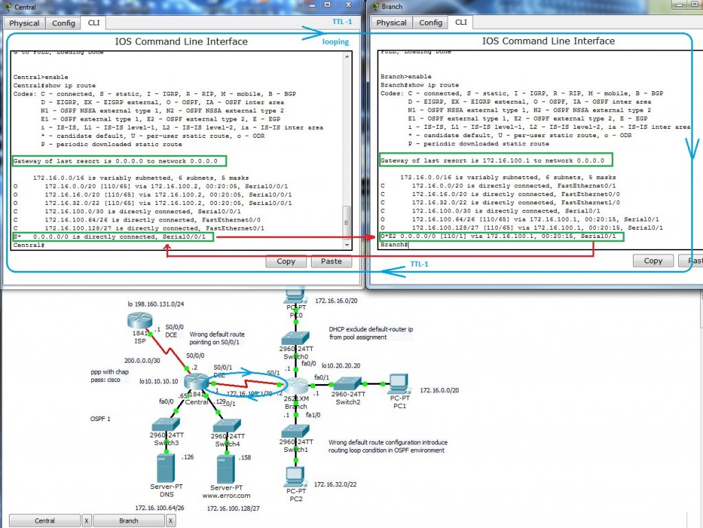
Network topology consist of central router (act as boundary between office network and WAN) and one branch router (for simplicity is there only one branch router). All end devices are on separate networks and private address space is in use in internal network. Wrong default route
ip route 0.0.0.0 0.0.0.0 serial0/0/1 (correct it is serial0/0/0) introduce in network routing loop that we will examine.
Our lab include option for sending ping and follow what is happen. Toggle to simulation mode and Auto capture/play.
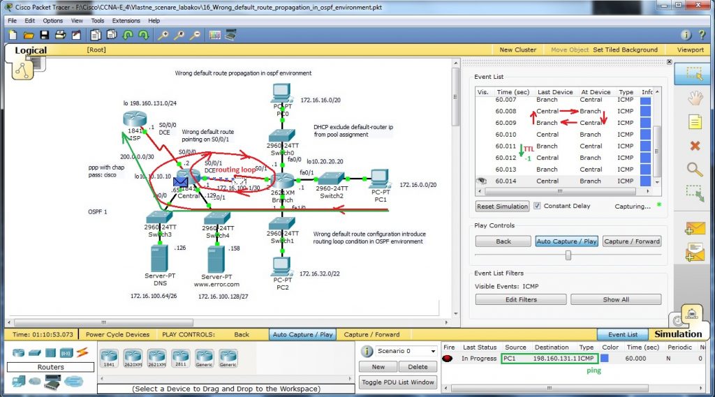
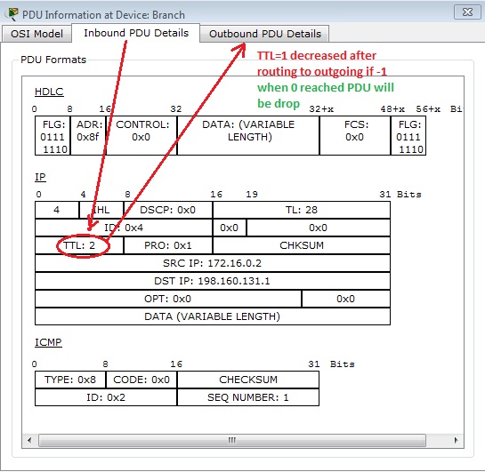
Wrong default route lead PDU to its origin and Branch router loop back to central router with default route. L3 PDU contain mechanism how to break endless looping of PDU – TTL in data packet header is decreased after L3 routing to appropriate interface as you can see on next picture (PDU examination in cisco packet tracer – simulation mode).
Output from most common troubleshooting command show ip route that output from routers routing table issued on both routers is:
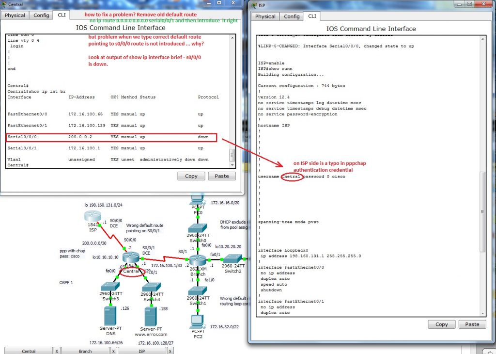
Now is time correct our mistake. What we need to do? At first you must remove wrong default route. There is no way how to change existing static route. First remove wrong route with command
no ip route 0.0.0.0 0.0.0.0 serial0/0/1
that point not to ISP router but back to internal Branch router and cause routing loop. Next step is introduce appropriate (correct) default route this way:
ip route 0.0.0.0 0.0.0.0 serial0/0/0
and now we going to examine output from show ip route. But you will obtain problem that is cause of my mistake. In routing table is not default route introduced. Keep in mind that static route (but all routes) is in output only when appropriate outgoing interface is on. Then we will examine up state of s0/0/0 interface. As you can see physical layer is Up but protocol is down.
S0/0/0 interface on Central router is connected to ISP with PPP link that use chap as authentication protocol. We need examine clock command on DCE end of serial link and then authentication credential on bot end of link.
And there is the problem, ISP side is supplied wit incorrect name of Central router. there is a typo Cnetral and correct it may state Central.
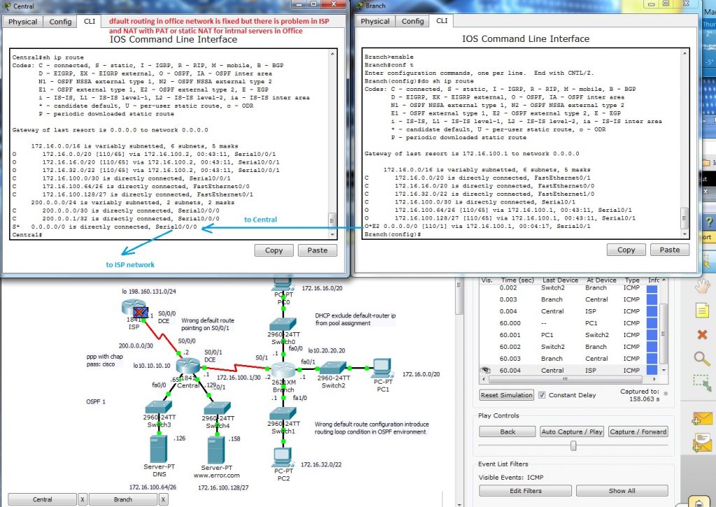
Default route is now correct but can we establish a connection between end devices on office network and ISP? Fire ICMP packet to destination nework 198.160.131.1. Packet can reach ISP router but then is discarded because no translation to public network have not been made. We are closer to our goal, data re well routed but address translation on private network boundary must be established.
For ISP (internet access – now without security configuration) connection in network with many clients I decided for NAT (network address translation) with PAT (port address translation) on interface s0/0/0.
At first we must create standard access list (i use named but also can be used numbered)
ip access-list standard NAT
permit 172.16.0.0 0.0.15.255
permit 172.16.16.0 0.0.15.255
permit 172.16.32.0 0.0.15.255
permit 172.16.100.0 0.0.0.3
and then enable nat translation with command
ip nat inside source list NAT interface s0/0/0 overload
most common beginners (also me) mistake is forget mark appropriate interface as ip nat inside and outside. in our case it is:
interface s0/0/0
ip nat outside
interface s0/0/1
ip nat inside.
Now we can place simple PDU between appropriate ends.
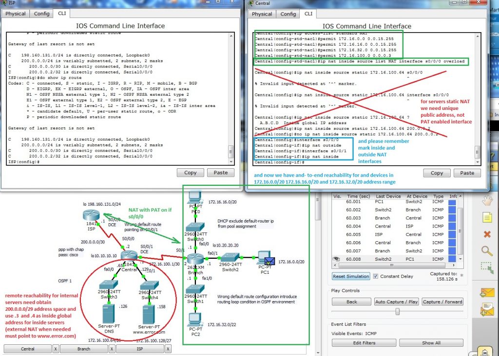
As „how to?“ training you can establish connection for inside servers and enable reach them from ISP side. There must be used static nat and address range for inside global must increase from 200.0.0.0/30 to minimal 200.0.0.0/29 as it state previews picture.
Final and fixed packet tracer lab is on next picture and for your training can be obtained from here (PKT 5.2 or above).