6. OSPF DR and BDR slection in multiaccess network segment examination lab.


Multi access networks create challenge for OSPF because:
a) create multiple adjacencies (one adjacencies for every pair of router)
b) extensive flooding of LSA – link state advertisement
for n -routers it is n(n-1)/2 adjacencies.
Because link-state protocols flood their link state packets during cold start or when there is a change in the topology possible solution is election of DR designated router.
DR – designated router in multi access network topology act as collector and distributor for LSAs. A BDR – backup designated router is elected in case the designated router fails. All other router become DROthers. Instead flooding LSA to all routers in multi access network, DROthers only send their LSAs to the DR and BDR using multicast address 224.0.0.6. The DR use multi access address 224.0.0.5. And the result is that only DR router flood all the LSAs in multi access network.
How are DR/BDR elected?
DR and BDR are elected this way:
1) DR – router with highest OSPF interface priority
2) BDR – router with second highest ospf priority
3) If ospf interfaces priorities are equal (default 1)., the highest router ID is used to break the tie.
To observe result of DR and BDR election results and neighbor adjacencies creation you can use
#show ip ospf neighbor
or per interface base
#show ip ospf interface fa0/0 (state, who is DR and who is BDR – their IPs).
When are DR and BDR elected?
Election take place as soon as the first router with ospf enabled interface is active on multi access network (powered in and network command is placed). When DR is elected, it remains DR until:
- DR fails
- OSPF process on DR fail
- the multi access interface on DR fails
When DR fail BDR assume their role and election is held to choose new BDR.
When you will that router you want become DR and BDR (if boot first with not highest router ID or interface priority, first election can select wrong router as DR and BDR):
- boot DR first, followed by BDR and next all other
- shut down all interfaces on all routers and now use no shutdown on DR, then BDR and then on all others
How to change ospf interface priority?
Selecting right routers to become DR and BDR is crucial because their are collectors of all LSAs and its important to have sufficient CPU and memory capacity. Better control for election process as use router-ID for tie breaking is use
r(config-if)#ip ospf priority {0 to 255}
- default is 1
- 0 make router ineligible to became DR or BDR
- router with highest interface priority – DR, second highest – BDR
Our preconfigured lab let you examine DR and BDR election process, you are encouraged introduce new physical links as you can see in next pictures from their creation. An show ip route show you best path selection when ospf as routing protocol is on use. Please remember how OSPF select preferred path, cisco ospf implementation use bandwidth. Cisco IOS uses the cumulative bandwidth of the outgoing interfaces from the router to the destination network as the cost (cost is associated with output side of each router interface and is ospf metric).
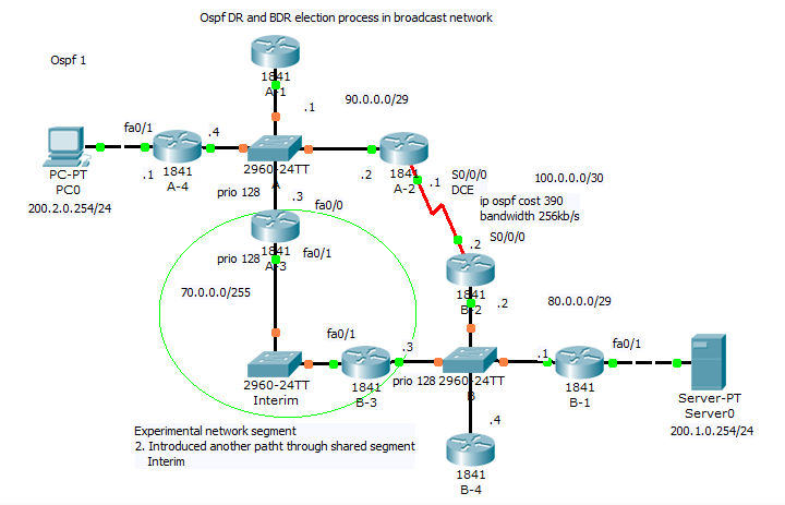
- Preconfigured scenario for our examination is here (PKT 5.2 or above is required) in their begining topology.
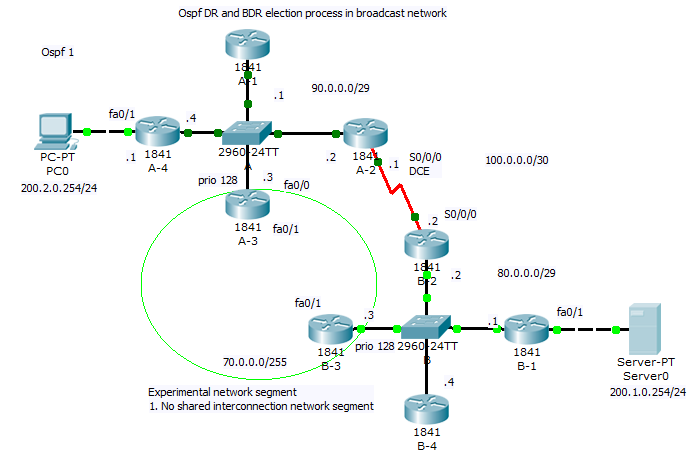
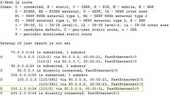
For best route selection process from network 200.2.0.0/24 PC0 to Server0 in network 200.1.0.0/24 use command show ip route on A-4 and B-1 routers. How are cumulative bandwidth increased in path introduced in routing table (best path to destination network) and DR, BDR election process is described next (click for better view).
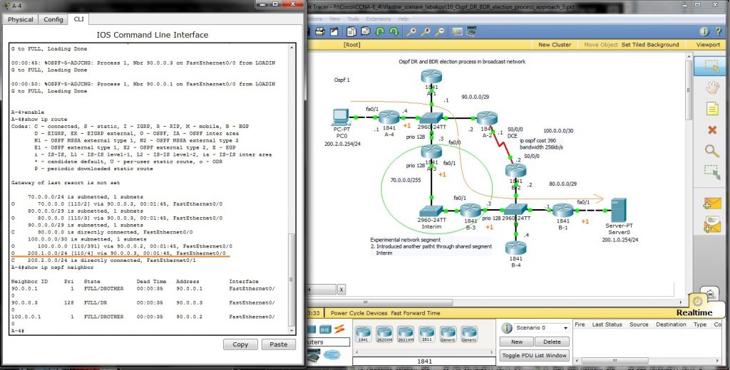
2. In our network introduce shared segment between A-3 and B-3 router – this PKT lab is here.
New path with lower cost will be preferred for packet delivery (examine route introduction for network 200.1.0.0./24 in router A-4). For DR selection in shared network segment introduced in this scenario was for marked interface used ip ospf priority 128 (interface command).
How is new metric (4) calculated and output form show commands follow
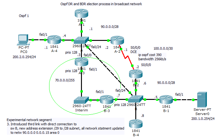
3) Our last scenario introduce new path that will be best (lowest cumulative cost of outgoing interfaces). But we must adjust our subnet range from /29 mask to new /28 and introduce new network commands network 90.0.0.0 0.0.0.15 area 0 to accommodate our experiment. You are encouraged collect output from show commands and compare them against your theoretical results.
Final configuration for our lab can be obtain here (as earlier PKT 5.2 or above is required).
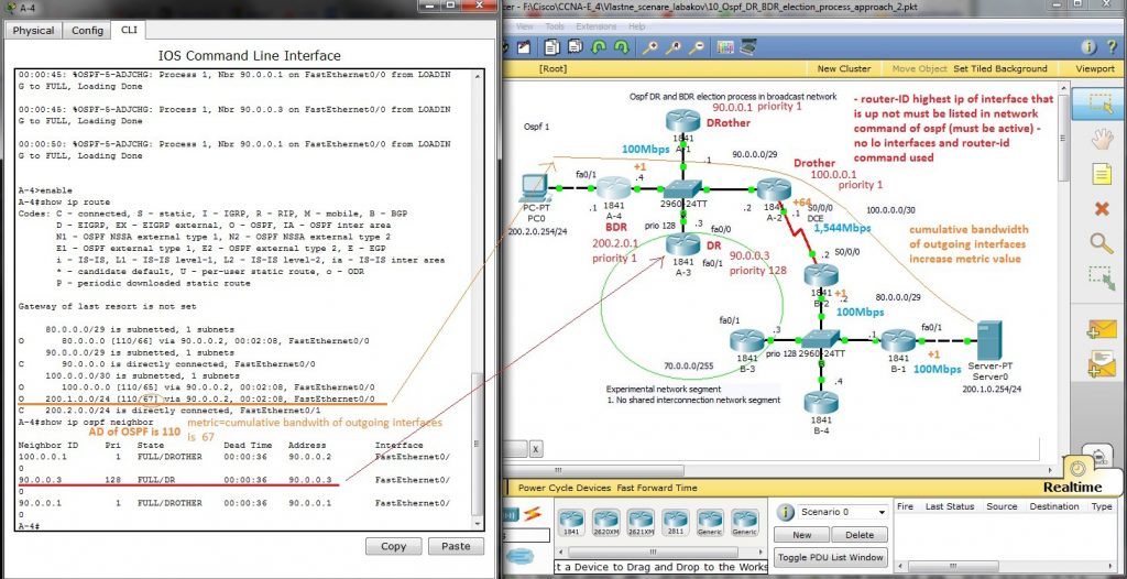
Explanation of DR, BDR selection and cumulative bandwidth calculation for best path is on next picture, Router -IDs are included in picture (no lo interface and router -id command was issued on any router – then higher ip of any active interface is used for ospf router-ID derivation).
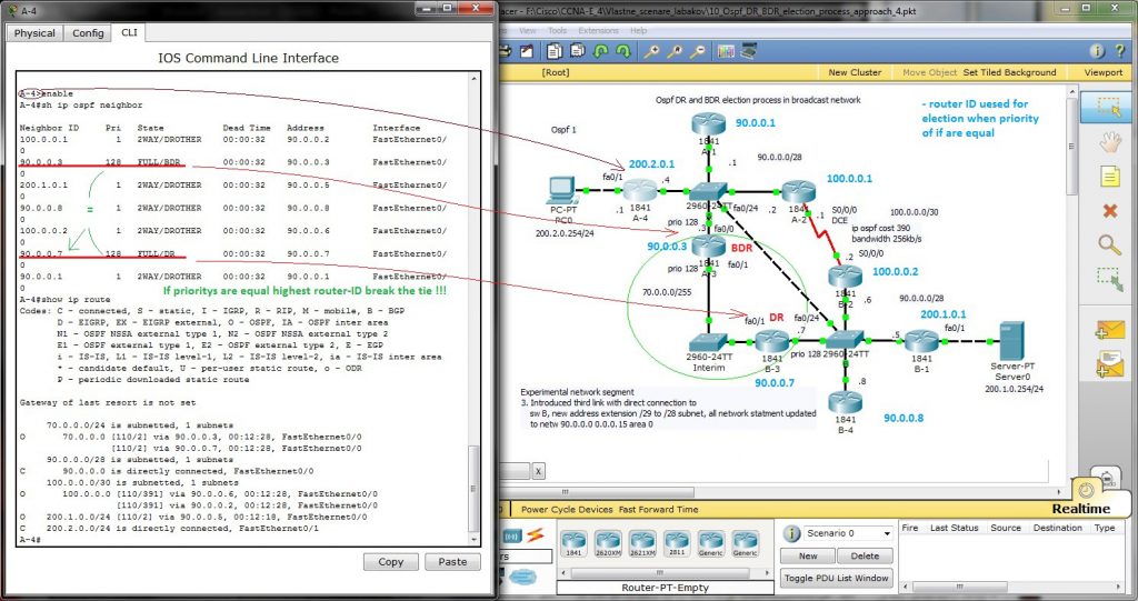
Output from show ip route entered in router A-4 is